Detachable fluid cooling system for bicycle disc brake

a technology of disc brake and cooling system, which is applied in the direction of cycle brakes, bicycle equipment, hoisting equipment, etc., can solve the problems of bicycle wheels locking up, bicycle riders being thrown off the bicycle, and hydrostatic or actuating fluid becoming overheated

Inactive Publication Date: 2001-03-06
SHIMANO INC
View PDF27 Cites 18 Cited by
  • Summary
  • Abstract
  • Description
  • Claims
  • Application Information

AI Technical Summary

Problems solved by technology

However, one problem with disc brakes is that the hydraulic or actuating fluid can become overheated such that vapor-lock occurs.
When vapor-lock occurs, the bicycle wheels can lock up and throw the rider off of the bicycle.
These prior art methods of avoiding vapor-lock have many problems.
One particular problem, is that these solutions often are expensive to manufacture.
Also, some of these prior art solutions are not completely effective.

Method used


Image

  • Detachable fluid cooling system for bicycle disc brake
  • Detachable fluid cooling system for bicycle disc brake
  • Detachable fluid cooling system for bicycle disc brake

Examples


third embodiment

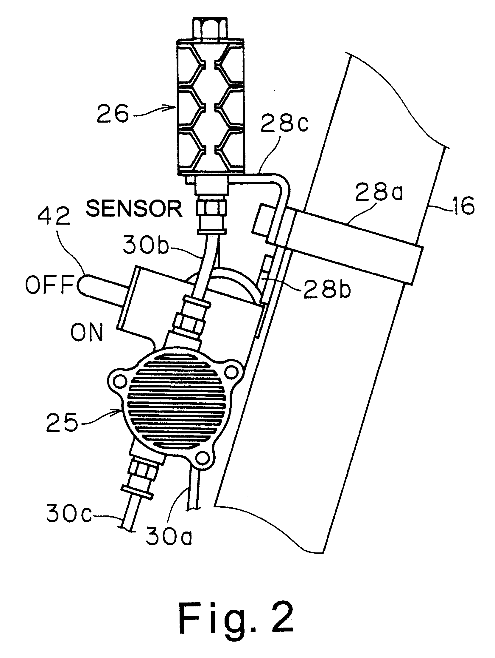
Referring now to FIG. 14, a simplified cooling system 220. Basically, cooling system 220 includes coolant member 224, coolant bottle or tank 226, an on / off valve 227 and a pressure release valve 228. Disc brake caliper 221 is substantially identical to disc brake caliper 21 discussed above, except that a coolant gauge 229 has been added to the integral coolant member 224 to visually inspect the amount of coolant or water contained within coolant member 224.

In view of the similarities between disc brake caliper 221 and disc brake caliper 21 of the first embodiment, disc brake caliper 221 will not be discussed or illustrated in detail herein. Moreover, it will be apparent to those skilled in the art from this disclosure that disc brake caliper 221 can be utilized on bicycle 10 of the first embodiment so as to be operated by brake operating mechanism 23 of the first embodiment to engage brake disc 22.

In this embodiment, cooling system 220 is designed such that the rider can manually ad...

fourth embodiment

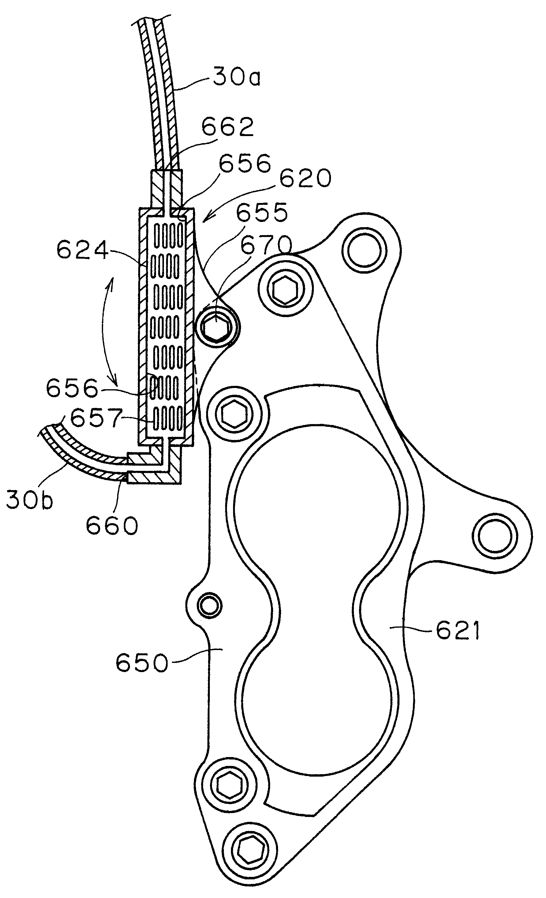
As seen in FIG. 15, a modified disc brake caliper 321 is illustrated. Disc brake caliper 321 is substantially identical to disc brake caliper 21 of the first embodiment except that the internal coolant member 324 is a closed unit, which has a high specific heat gel located therein. While coolant member 324 is illustrated as being detachable, it will be apparent to those skilled in the art from this disclosure that coolant member 324 can be made integral with housing 350. Thus, this system is a simplified version of the first embodiment. The high specific heat gel located in coolant member 324 can be any high specific heat gel, which can operate under the normal operating conditions of a bicycle disc brake.

In view of the similarities between disc brake caliper 321 and disc brake caliper 21 of the first embodiment, disc brake caliper 321 will not be discussed or illustrated in detail herein. Moreover, it will be apparent to those skilled in the art from this disclosure that disc brake...

fifth embodiment

Referring now to FIG. 16, a modified disc brake caliper 421 is illustrated in accordance with the present invention. In this embodiment, the coolant inlet opening 460 and coolant outlet opening 462 are interconnected together via a transparent conduit 430. This transparent conduit 430 allows the rider to inspect the coolant level within the coolant member 424. Also, a pressure release valve / refill valve 428 has been added such that additional coolant or fluid can be added as needed and / or steam or coolant vapor be released from the coolant member 424.

Disc brake caliper 421 is substantially identical to disc brake caliper 21 except that disc brake caliper 421 has transparent conduit 430 extending between its inlet opening 460 and coolant outlet opening 462 and pressure release valve / refill valve 428 has been added. In view of the similarities between disc brake caliper 421 and disc brake caliper 21 of the first embodiment, brake disc caliper 421 will not be discussed or illustrated i...


PUM


Abstract

A bicycle disc brake caliper is provided with a detachable cooling system that transfers heat away from the actuating fluid. Basically, the bicycle disc brake caliper has a housing and a piston unit, with a coolant member of the cooling system attached to the housing. The housing has a frame mounting member sized to be coupled to a portion of a bicycle frame. The piston unit is movably coupled to the housing between a release position, in which the piston unit is spaced from a brake disc mounted to a wheel of a bicycle, and a braking position, in which the piston unit engages the brake disc of the bicycle wheel. The coolant member has a coolant area for receiving coolant to create a coolant heat sink that transfers heat from the housing. The housing has an actuating passage in fluid communication with the piston unit to move the piston unit via an actuating fluid. In one embodiment, the cooling system includes a pump and a reservoir. In another embodiment, a coolant or water bottle is attached to the coolant member for manually adding coolant thereto. In another embodiment, the coolant member is filled with a high specific heat gel.

Description

1. Field of the InventionThis invention generally relates to cooling a bicycle disc brake for stopping rotation of a bicycle wheel of a bicycle. More specifically, the present invention relates to a detachable fluid cooling system, which is adapted to be coupled to a disc brake of a bicycle.2. Background InformationBicycling is becoming an increasingly popular form of recreation as well as a means of transportation. Moreover, bicycling has become a very popular competitive sport. Whether the bicycle is used for recreation, transportation or competition, the bicycle industry is constantly improving their components. One particular component of the bicycle which has been extensively redesigned over the past years is the braking systems of bicycles.There are several types of bicycle brake devices, which are currently available on the market. Examples of some types of common bicycle brake devices include rim brakes, caliper brakes and disc brakes. If a rider wants a very high performanc...

Claims


Application Information

Patent Timeline
Patent Type & Authority Patents(United States)
IPC IPC(8): B62L3/00B62L3/02B62L1/00B60T5/00F16D65/853F16D65/00F16D55/228F16D55/22F16D65/78F16D66/00F16D55/00F16D65/02F16D65/84
CPCB60T5/00B62L1/00B62L1/005B62L3/02B62L3/023F16D55/228F16D65/853F16D2055/0091F16D2065/781F16D2065/783F16D2065/784F16D2065/787F16D2066/001
Inventor NAKAMURA, YASUSHI
Owner SHIMANO INC
Why Eureka
Try Eureka