
Compact device for metering gas at variable pressure

Inactive Publication Date: 2001-03-13
GDF SUEZ SA
View PDF8 Cites 51 Cited by
  • Summary
  • Abstract
  • Description
  • Claims
  • Application Information

AI Technical Summary

Benefits of technology

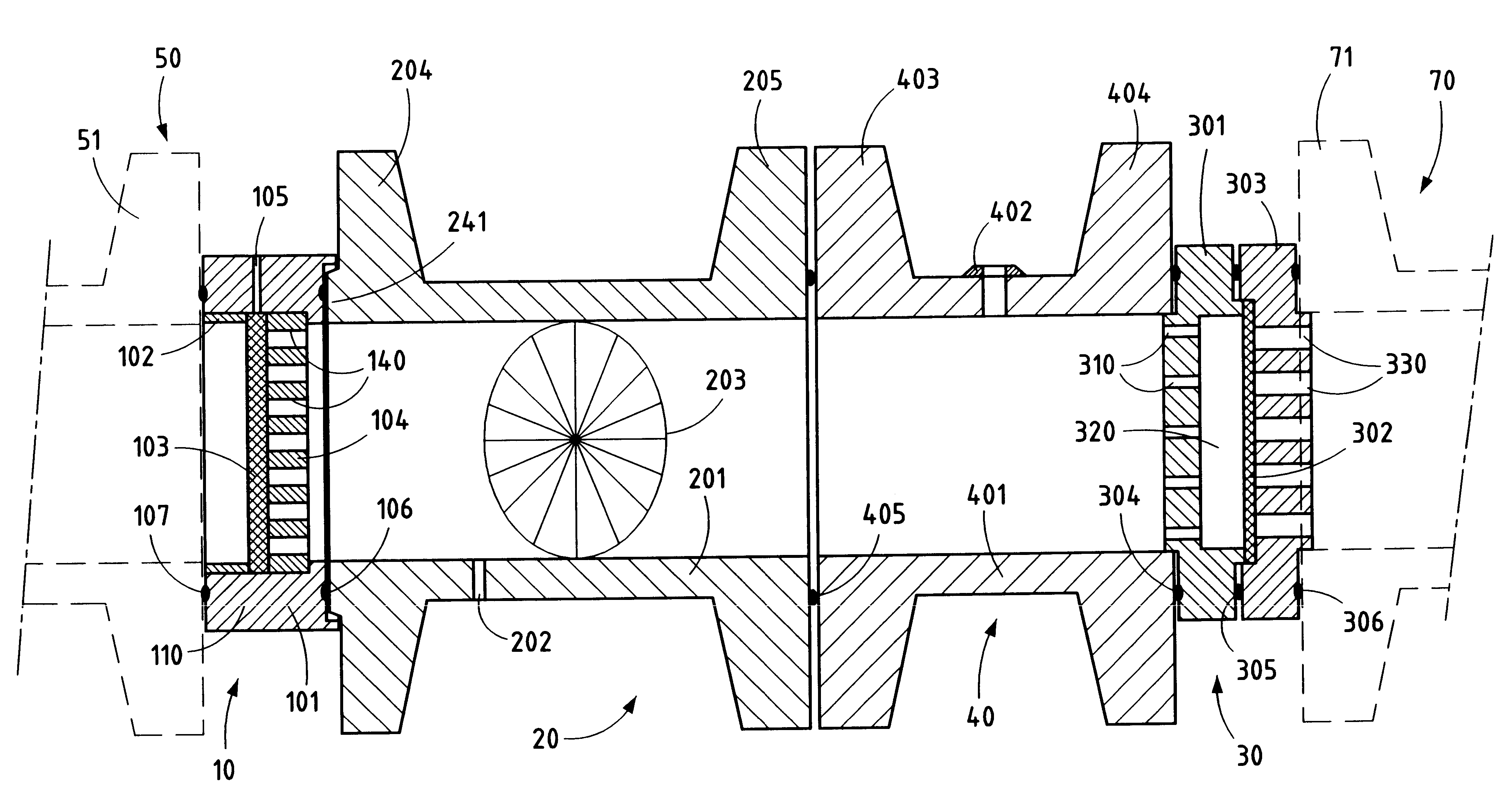
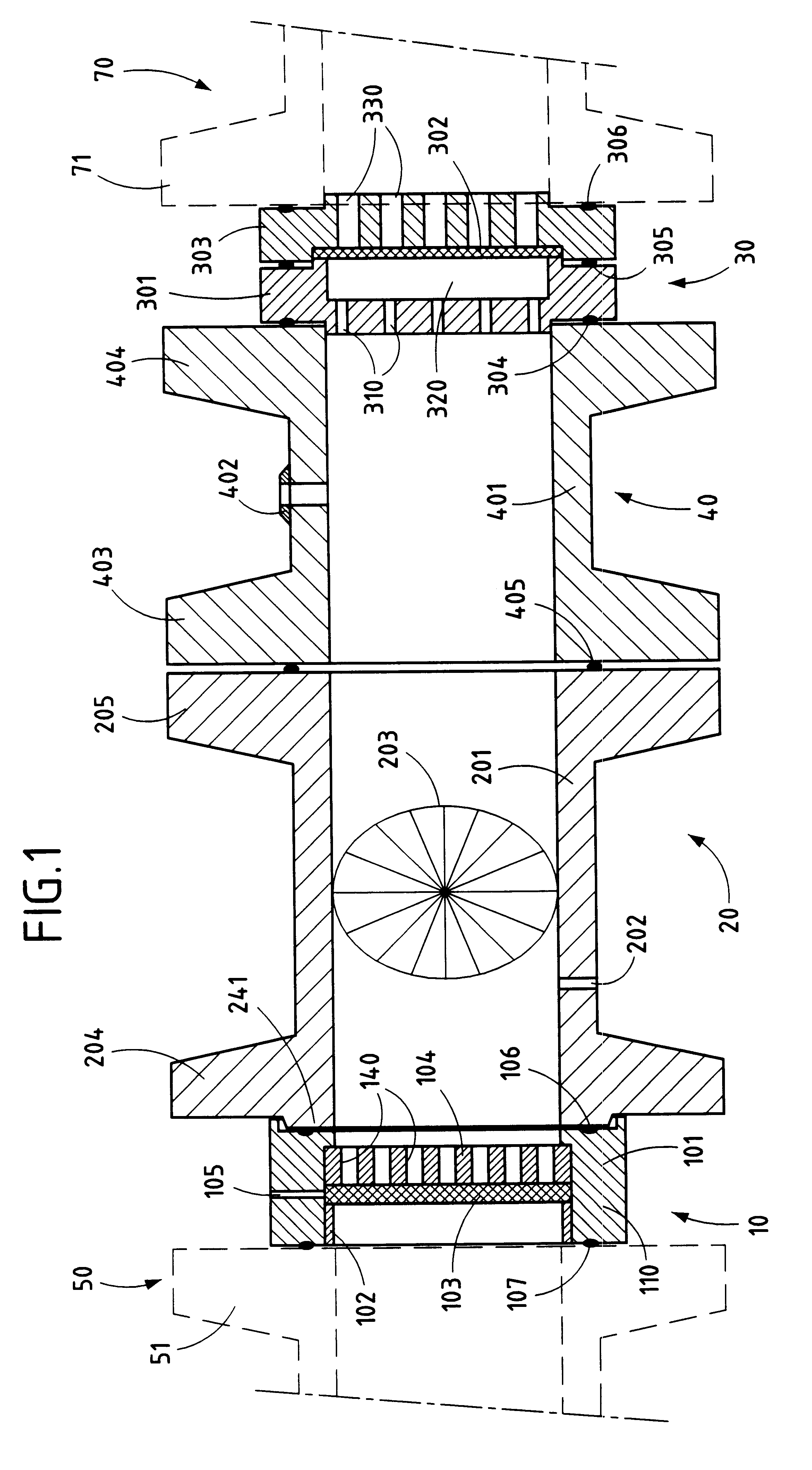
The present invention seeks to remedy the above-mentioned drawbacks and to make it possible to implement a gas distribution station and a gas metering device which are compact while also being modular, suitable for easily incorporating conventional expander-regulators or conventional meters, and implementing gas flow straightener elements or flowrate limiters of a structure that simplifies manufacture while guaranteeing robustness and a high level of safety in operation.
The presence of an empty space between the second perforated plate and the second porous plate provides better control over the flow coefficient of the limiter in that under critical conditions the porous plate does not disturb the establishment of the sonic throat at each hole. Experiments have shown that such a sonic throat can become established, when cylindrical orifices are used, at the outlet from the orifice, in the narrowest portion of the gas stream (vena contracta) at a distance of the same order as the diameter of the hole. The porous body then comes downstream to attenuate the noise generated by the shockwaves due to the gas being recompressed and due to turbulence.

Problems solved by technology

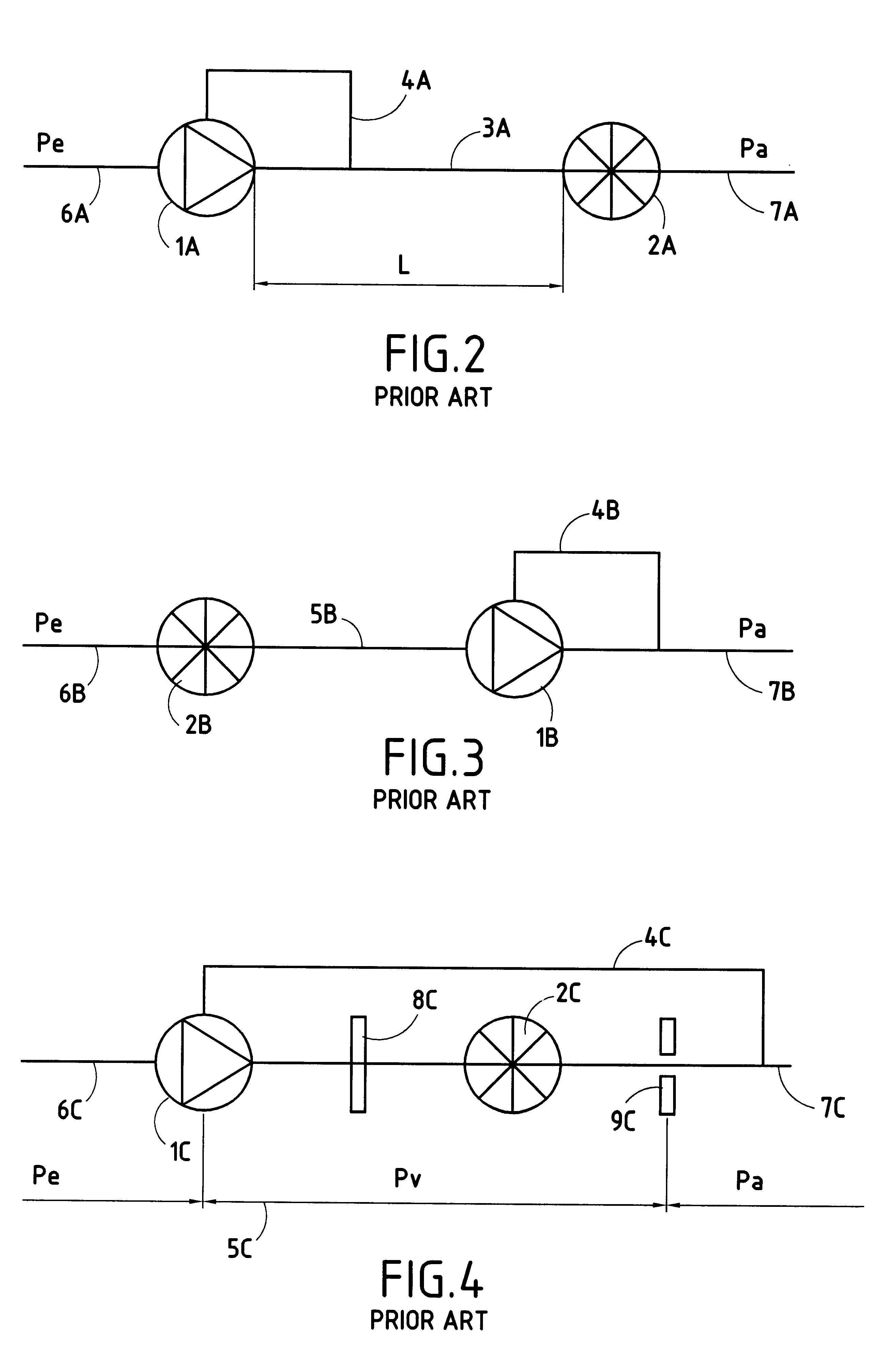
However in solution A (metering downstream from expansion) as in solution B (metering upstream from expansion), the link pipes connecting the inlet of the station or the pressure expander-regulator to the meter, e.g. a spinner meter, generally adds additional disturbances due to the particular shape of the link pipes and to the accessories that may be mounted on the link pipes.
The flowmeter can thus receive a flow of gas whose velocity profile is deformed or which has a gas stream that is subject to rotation, which is prejudicial to the quality of metering.
This leads to low flow rates being metered poorly.
Consequently, in certain situations, there is a risk of the meter being damaged by its maximum flow rate being temporarily exceeded.
This leads in particular to a special and relatively complex design for the flow straightener 8C and the limiter 9C, in particular.

Method used


Image

  • Compact device for metering gas at variable pressure
  • Compact device for metering gas at variable pressure
  • Compact device for metering gas at variable pressure

Examples


Embodiment Construction

The variable pressure gas metering device of the invention relies on the operating principle shown with reference to FIG. 4, however it includes a set of modular subassemblies which are not incorporated in a common housing, unlike the embodiments described in document EP-A-0 337 887. In addition, the configuration of the module constituting the straightener and that of the module constituting the flowrate limiter, as described below, are adapted to facilitate implementation and to ensure high reliability in operation.

For a variable pressure metering device, the value of the overall flow rate coefficient Q of the limiter is less than or equal to the maximum flow rate of the meter so that regardless of operating conditions, it is never subjected to a flow greater than its capacity. Thus, the speed of the gas through the meter does not exceed the nominal maximum value corresponding to the nominal flow rate of the meter. The pressure Pv at the meter can thus vary between the delivery pr...


PUM


Abstract

The device for metering the volume of gas flowing in a pipe, downstream from an expander-regulator, comprises in succession a flow straightener, a velocity-measuring flowmeter, and a silent flowrate limiter. The straightener comprises a support ring in which there are mounted a first perforated plate having holes distributed over its surface, together with a first porous plate and a spacer in the form of an annulus co-operating with the first perforated plate. The limiter comprises an upstream web defining a second perforated plate perforated by a defined number of calibrated holes, the total flow section thereof being much less than the total flow section of the first perforated plate, a second perforated plate, and a downstream web defining a third perforated plate having holes of total flow section that is much greater than the total flow section of the second perforated plate of the upstream web.

Description

The present invention relates to a compact variable-pressure gas metering device for metering a volume of gas flowing along a pipe, downstream from an expander-regulator, and comprising in succession a flow straightener, a velocity-measuring flowmeter, and a silent flowrate limiter.The invention relates more particularly to a device applicable to a gas distribution station performing the functions of expanding and regulating the delivery pressure of gas and of metering the volumes of gas delivered.In a conventional solution, as shown in FIG. 2, the gas flowing in a pipe 6A at an upstream pressure Pe is expanded from the upstream pressure Pe to a regulated downstream pressure Pa in an expander-regulator 1A which receives a control signal via a line 4A starting from a segment of pipe 3A situated downstream from the expander-regulator 1A. A meter 2A is disposed between pipe segment 3A and a downstream distribution pipe 7A. The meter 2A meters the volume of gas consumed at the downstrea...

Claims


Application Information

Patent Timeline
IPC IPC(8): G01F1/05G01F1/08G01F15/00G01F15/04G01F1/12G01F1/00F16L55/04
CPCG01F1/08G01F1/12G01F15/04G01F15/00
Inventor CORNIL, JEAN-PHILIPPEDUTERTRE, DOMINIQUEMODE, LAURENTDE LAHARPE, VINCENT
Owner GDF SUEZ SA
Learn More