Cutting plotter equipped with device for reading register marks for seal cutting and method for reading register marks using same

a technology of register marks and cutting boards, applied in the field of cutting plotters, can solve problems such as critical problems, and achieve the effect of accurate reading

Inactive Publication Date: 2001-03-13
MIMAKI ENG
View PDF8 Cites 26 Cited by
  • Summary
  • Abstract
  • Description
  • Claims
  • Application Information

AI Technical Summary

Benefits of technology

In contrast to this, when, for example, an unnecessary colored line is printed on a surface of a portion of the seal material near one of the second and subsequent register marks or a stain is caused on the surface of the portion of the seal material, the amount of light reflected from a surface of the colored line or that of the stain is, for example, as small as 30% or the like, so that a difference between the amount of light reflected from the surface of the colored line or that of the stain and the amount of light reflected from a surface of a portion of the seal material, which is defined near the colored line or stain and of which a ground color is exposed, is greater or smaller than the difference in the amounts of reflected light stored in the storage means. This causes a relative difference between the difference in the amounts of reflected light stored in the storage means and the difference in the amounts of reflected light which is calculated by the second calculation means to be outside the predetermined tolerance. This results in the fact that the colored line or stain is not the register mark printed on the seal material being correctly judged by the determination means. Thus, this prevents the colored line or stain from being mistaken for one of the second and subsequent register marks printed on the surface of the seal material.
Further, even when any situation, such as lack of gloss of the surface of the register mark printed on the seal material, color fading of the register mark or the like, causes the amount of light reflected from the surface of the register mark to be increased to a level as high as 30%, or even when any situation, such as lack of gloss of the portion of the seal material which is positioned near the register mark and of which a ground color is exposed, dullness of the portion or the like, causes the amount of light reflected from the portion of the seal material to be decreased to a level as low as 70%, the difference between the amount of light reflected from the surface of each of the second and subsequent register marks and the amount of light reflected from the portion of the seal material, which is near the respective one of the register marks and of which a ground color is exposed, is permitted to be substantially identical with the difference in the amounts of reflected light stored in the storage means and obtained from the amount of light reflected from the surface of the first register mark formed of the same printing pigment under the same conditions as the second and subsequent register marks and the amount of light reflected from the portion of the seal material which is near the first register mark and of which a ground color is exposed. This results in the relative difference between the difference in the amounts of reflected light stored in the storage means and the difference in the amounts of reflected light between the amount of light reflected from the surface of each of the second and subsequent register marks and the amount of light reflected from the portion of the seal material, which is near the respective one of the register marks and of which a ground color is exposed, being permitted to be within the predetermined tolerance, when the relative difference is calculated by the second calculation means. This permits the determination means to accurately determine that the second and subsequent register marks are actually printed on the portions of the seal material on which they are supposed to be printed. As a result, the second and subsequent register marks can be accurately read without any mistake.

Problems solved by technology

However, when the cutting plotter including such a register mark reading unit as described above is to read each of the register marks 30 which is actually printed on the portion of the seal material 10 on which it is supposed to be printed on the basis of the difference between the amounts of reflected light detected by the light receiving element, it encounters a critical problem.

Method used


Image

  • Cutting plotter equipped with device for reading register marks for seal cutting and method for reading register marks using same
  • Cutting plotter equipped with device for reading register marks for seal cutting and method for reading register marks using same
  • Cutting plotter equipped with device for reading register marks for seal cutting and method for reading register marks using same

Examples


Embodiment Construction

Now, the present invention will be described hereinafter with reference to the accompanying drawings.

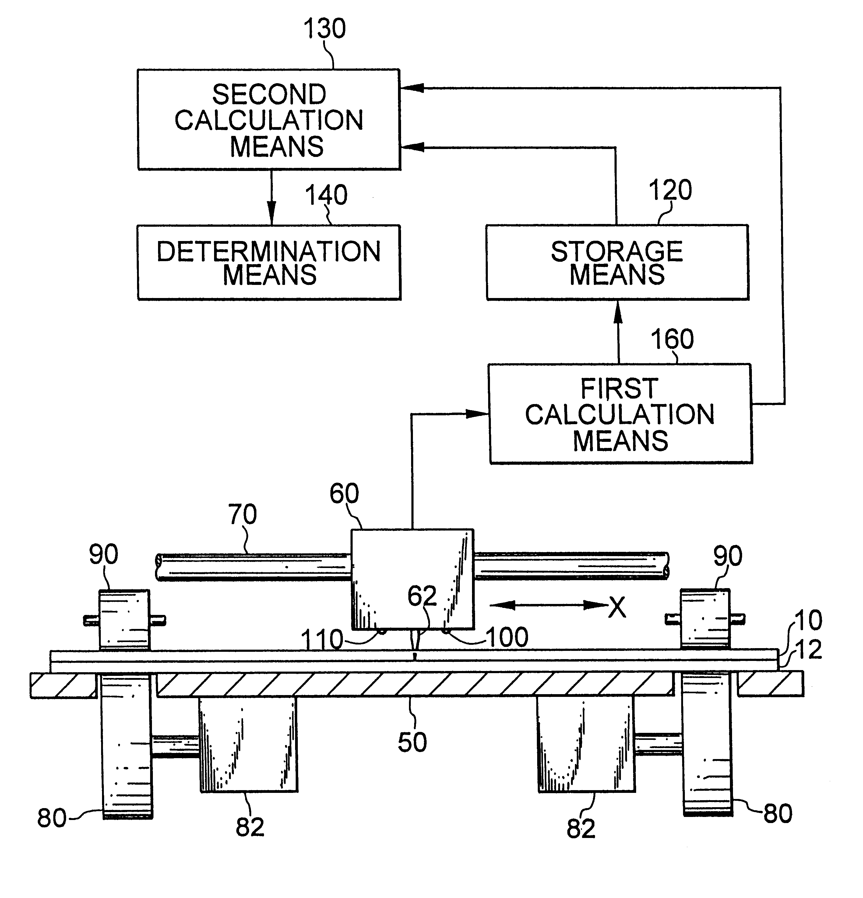
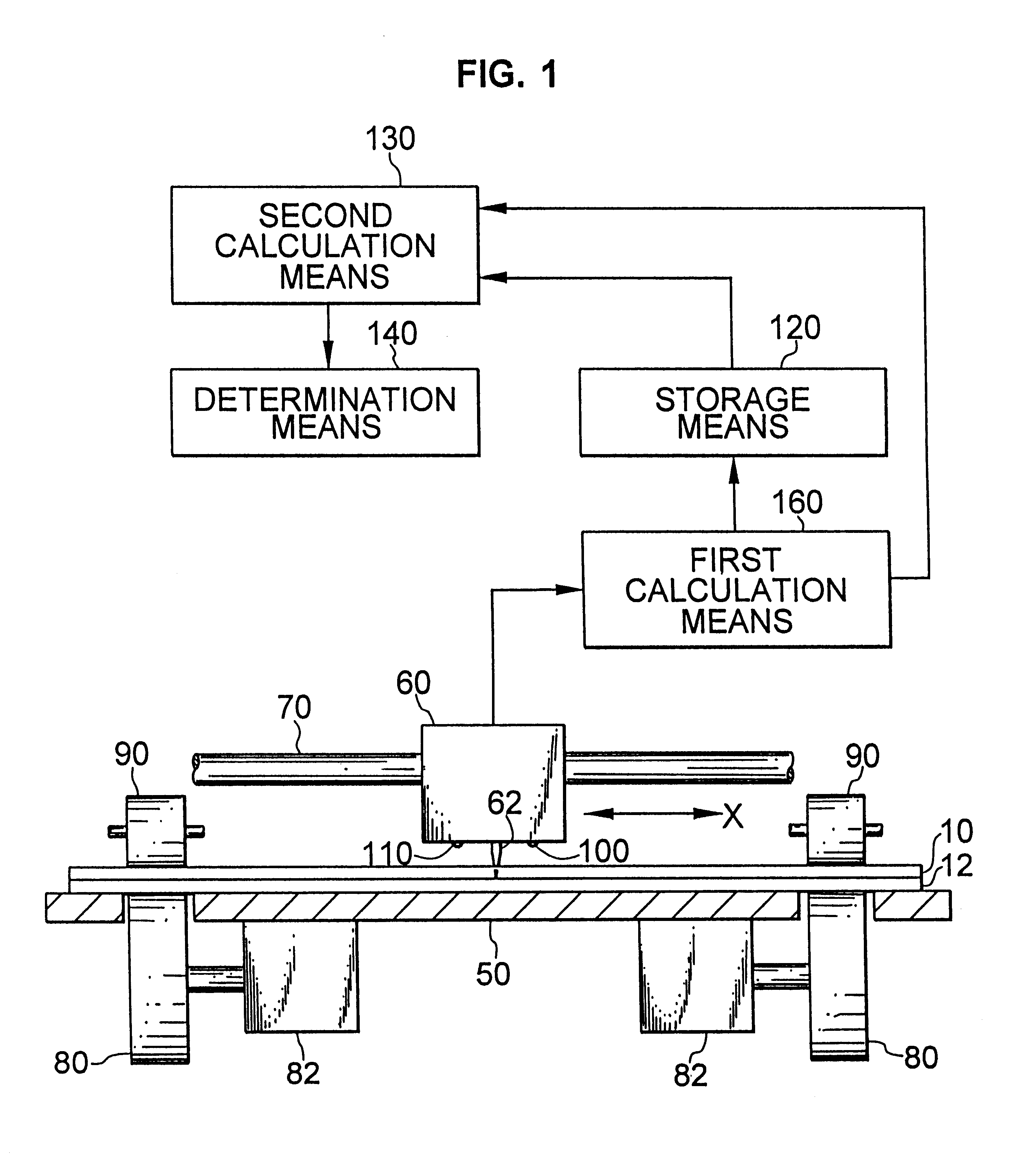
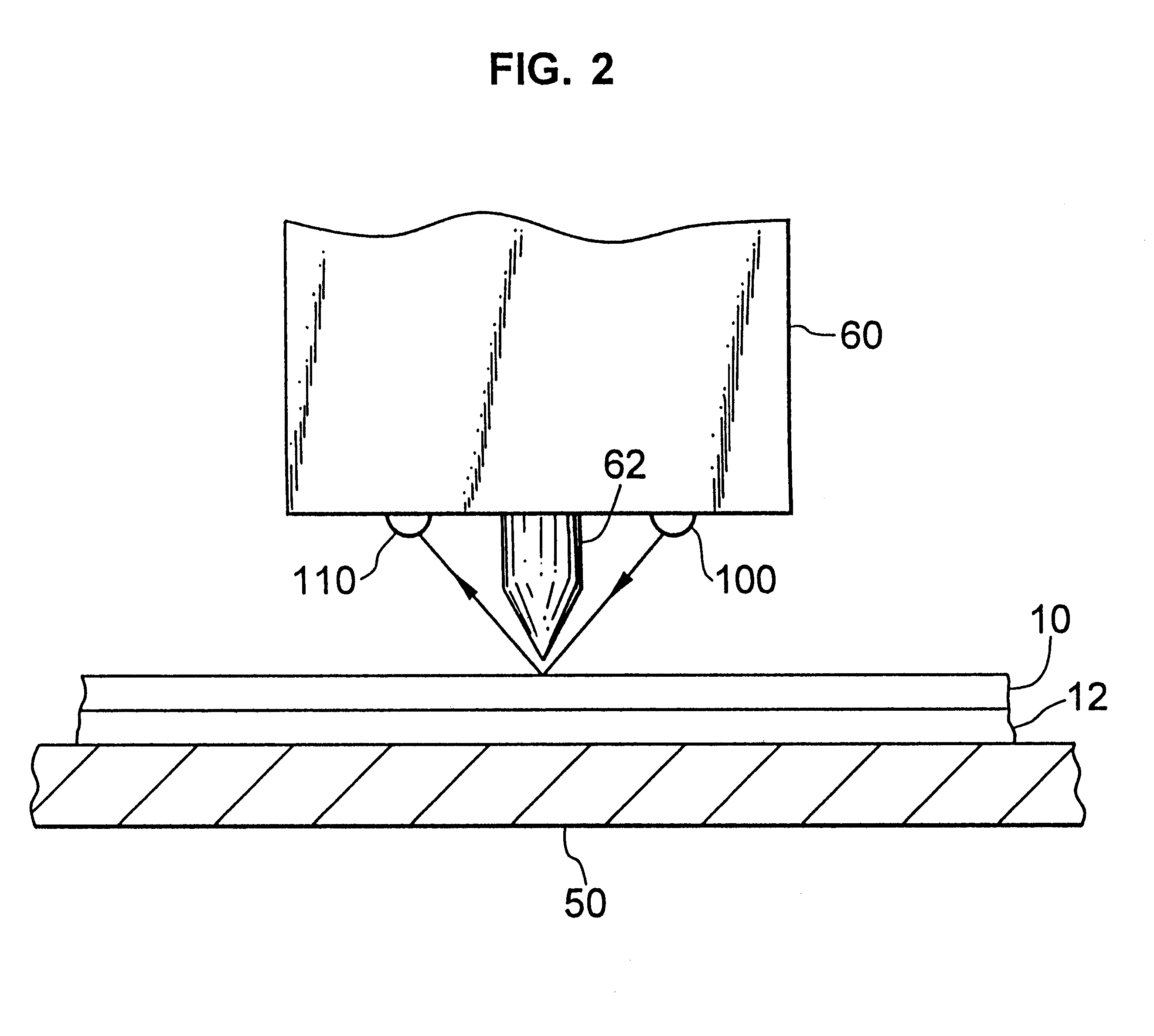
Referring first to FIGS. 1 and 2, an embodiment of a cutting plotter according to the present invention is illustrated. In FIGS. 1 and 2, reference numeral 50 designates a platen on which a seal material 10 is placed. The platen 50 has an upper surface finished smoothly to permit the seal material 10 to be smoothly slidable thereon. A head 60 is supported above the platen 50 through a guide rail 70 in a manner to be movable in an X-direction. The head 60 is mounted thereon with a cutter 62 in a manner to face a cutting edge thereof toward the platen 50.

The platen 50 is provided on opposite sides thereof with pinch rollers 90 and feed rollers 80 arranged in pairs in a manner to be vertically opposite to each other with the platen 50 being interposed therebetween. In the illustrated embodiment, the feed rollers 80 are arranged below the platen 50 and therefore the pinch rollers 90 are ...


PUM


Abstract

A cutting plotter equipped with a device for reading register marks for seal cutting capable of accurately reading the register marks printed on a seal material. The cutting plotter includes a head provided thereon with a light emitting element for emitting a predetermined amount of light toward a surface of the seal material and a light receiving element for detecting the amount of light reflected from the surface of the seal material. A difference between the amounts of reflected light detected by the light receiving element is calculated by a first calculation unit and then stored in a storage unit. A relative difference between the difference in the amounts of reflected light stored in the storage unit and a difference between the amounts of reflected light calculated by the first calculation unit is calculated by a second calculation unit. Also, a determination unit is arranged so as to determine whether or not the relative difference calculated by the second calculation unit is within a predetermined tolerance, to thereby determine whether or not the register marks are printed on the seal material.

Description

BACKGROUND OF THE INVENTION1. Field of the InventionThis invention relates to a cutting plotter equipped with a device for reading register marks for seal cutting and a method for reading the register marks by means of the plotter, and more particularly to a cutting plotter including a device for reading register marks for seal cutting which are used for cutting stickers or seals printed on a seal material along respective contours thereof and a method for reading the register marks using the cutting plotter.2. Description of Related ArtNow, the prior art will be described hereinafter with reference to FIG. 6. In FIG. 6, reference numeral 10 designates a seal material having a plurality of seals 20 printed thereon in a row. The seals 20 are each provided on a surface thereof with any desired characters, numerals, symbols, figures, pictures or the like. The seal material 10 is releasably adhered to a base sheet (not shown).The seal material 10 also has register marks 30 for seal cutt...

Claims


Application Information

Patent Timeline
Patent Type & Authority Patents(United States)
IPC IPC(8): B23Q15/20B23Q15/22B26F1/38B26D5/00B43L13/00B26D5/34G06T1/00
CPCB23Q15/225B26D5/005B26D5/34B26F1/3806G05B2219/42222
Inventor KOUCHI, YUJIKOBAYASHI, HISAYUKI
Owner MIMAKI ENG
Why Eureka
Try Eureka