Truck traffic monitoring and warning systems and vehicle ramp advisory system

Inactive Publication Date: 2001-03-20
INTERNATIONAL ROAD DYNAMICS
View PDF39 Cites 272 Cited by
  • Summary
  • Abstract
  • Description
  • Claims
  • Application Information

AI Technical Summary

Benefits of technology

The present invention yet still further provides a method of automatically controlling the operation of a traffic signalling device which is associated with a curve by analyzing data from any of the systems as disclosed above, the method comprising the steps of (i) downloading, into a processor, a set of records of including rollover threshold data and the speed of the truck derived from a first set of above-road electro-acoustic sensor arrays which is disposed upstream of the curve; (ii) downloading, into the processor, a set of records of a computed speed of the truck downstream of the first set of above-road electro-acoustic sensor arrays but upstream of the curve; (iii) matching records, by the processor, of the two speeds of the truck from both sets of records; (iv) computing, by the processor, and from the sets of records, an actual speed of the truck and a computed maximum safe threshold speed to prevent the truck from rollover from the rollover threshold data which has been downloaded into the processor; (v) computing, by the processor, a computed speed of the truck at the point of curvature of the curve; (vi) automatically operating, by the processor, the traffic signalling device if the computed actual speed of the truck exceeds the computed maximum safe threshold speed of the truck, to display a warning to a driver of the truck when the computed actual speed of the truck exceeds the computed maximum safe threshold speed of the truck; and (vii) discontinuing, by the processor, operating the traffic signalling device if the computed actual speed of the truck no longer exceeds the computed maximum safe speed for the truck.
The present invention still yet further prov

Problems solved by technology

The use of wire loops was, however, disadvantageous for several reasons.
First, a wire loop system did not detect a motor vehicle unless the motor vehicle included sufficient ferromagnetic material to create a noticeable perturbation in the inductance in the wire loop.
Because the trend now is to fabricate motor vehicles with non-ferromagnetic alloys, plastics and composite materials, wire loop systems will increasingly fail to detect the presence of motor vehicles.
Another disadvantage of wire loop systems was that they were expensive to install and maintain.
Often too, harsh weather precluded this operation for several months.
The Hendricks system did not teach the use of electro-acoustic transducers, but instead used pressure-sensitive detectors.
However, this patent used only a single electro-acoustic transducer for receiving acoustic signals within a detection zone, and did not teach spatial discrimination circuitry for representing acoustic energy emanating from a detection zone.
Consequently, speed-limited signals were only produced by signal display arrangements to warn the overtaking vehicle if there was a real risk of a collision.
However, this patent us

Method used


Image

  • Truck traffic monitoring and warning systems and vehicle ramp advisory system
  • Truck traffic monitoring and warning systems and vehicle ramp advisory system
  • Truck traffic monitoring and warning systems and vehicle ramp advisory system

Examples


Embodiment Construction

(A) Hazard Warning System

A generic aspect of the invention will now be described with reference to FIGS. 1 through 5. This generic aspect comprises a warning system which is installed at the approach to a hazard, whether it be a curve, an incline, a blind intersection, a traffic-signal controlled intersection, etc.

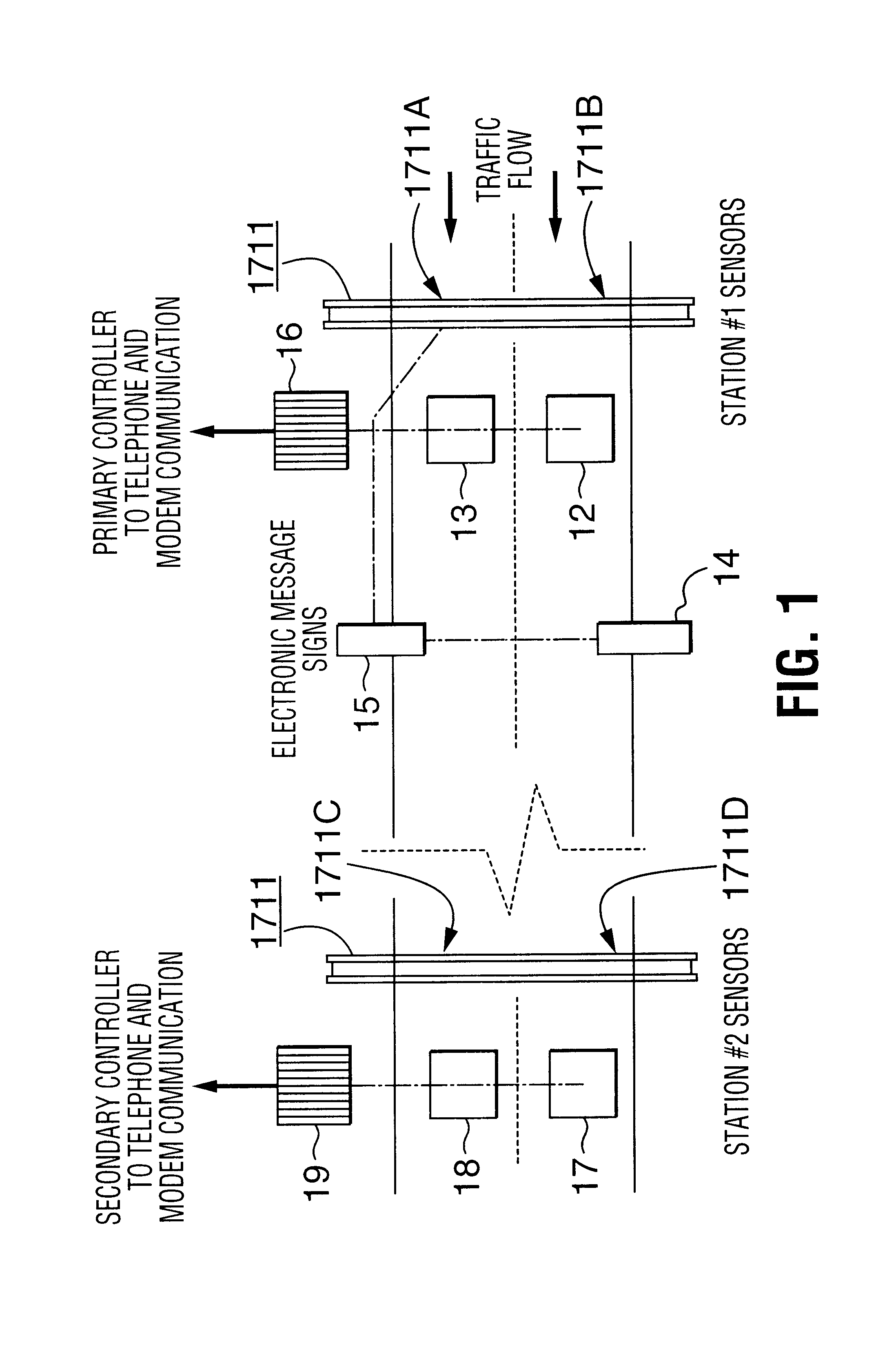
(i) Description of FIG. 1 and FIG. 2

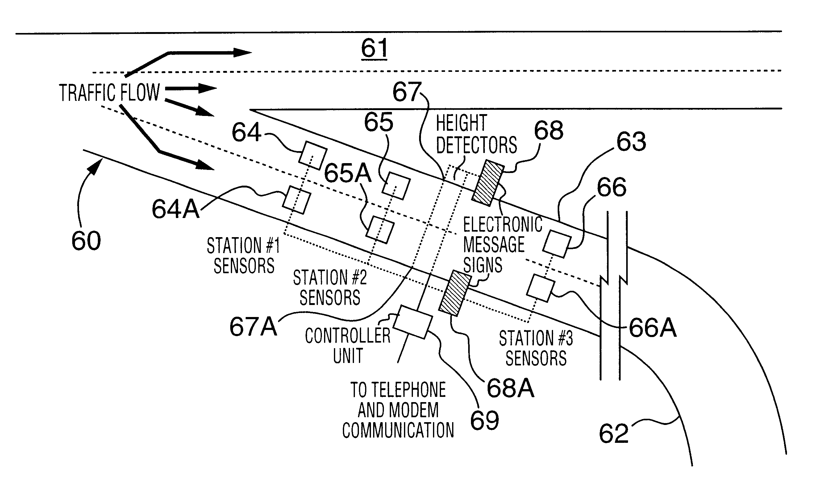
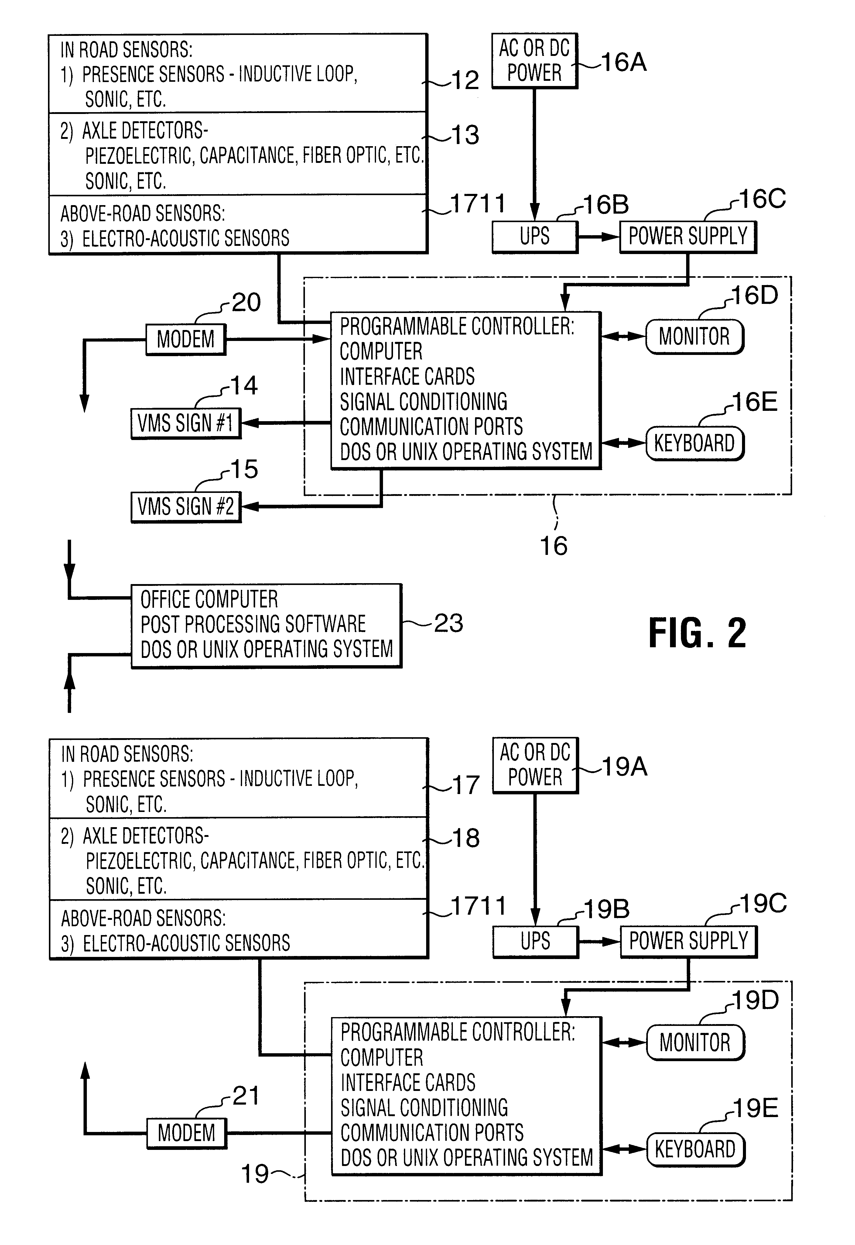
Referring to FIG. 1 and FIG. 2, the hazard warning system comprises, at a first sensor station, a first set of above-road electro-acoustic sensor arrays 1711, (namely, 1711A, 1711B) for detecting trucks by means of acoustic signals. The above-road electro-acoustic sensor arrays can determine whether the detected vehicle is a truck, or is not a truck, by an analysis of the sounds emanating from the detected vehicle. In addition, the truck may be classified dependent on its length, since the length of the vehicle can be determined by the length of time between the beginning of the detection of the vehicle and the ceasing of detection of th...


PUM


Abstract

Traffic monitoring and warning systems and vehicle ramp advisory systems are provided herein. Such system includes a set of sensor arrays comprising a set of above-road electro-acoustic sensor arrays which is disposed above a traffic lane approaching a hazard for producing signals which are indicative of whether the vehicle is an automobile or a truck and, if it is a truck, to record the presence of such truck, and to provide signals which are indicative of the speed of such truck. A processor is provided which has a memory for storing site-specific data related both to the geometry of the hazard and to signals which have been received from the set of above-road electro-acoustic sensor arrays. A traffic signalling device is associated with the traffic lane and is disposed downstream of the set of above-road electro-acoustic sensor arrays, the traffic signalling device being controlled by the processor. The processor is responsive to the signals from the set of above-road electro-acoustic sensor arrays for computing an actual speed of the truck and for computing a computed maximum safe speed for such truck at the hazard. The computed maximum safe speed of the truck is derived from the site-specific dimensional data of the hazard and from at least the initial speed of the truck, the computed maximum safe speed of the truck being a maximum safe speed for that truck safely to negotiate the hazard. The processor compares the computed actual speed of the truck with the computed maximum safe speed for the truck. Then, the processor automatically operates the traffic signalling device if the computed actual speed of the truck exceeds the computed maximum safe speed for the truck. The processor also discontinues operating the traffic signalling device if the computed actual speed of the truck no longer exceeds the computed maximum safe speed for the truck.

Description

(A) Field of the InventionThis invention relates to traffic monitoring systems including warning systems and vehicle ramp advisory systems, for monitoring commercial vehicles.(B) Description of the Prior ArtMany kinds of systems have been disclosed which monitor and / or control traffic. Typically, each highway department had a command centre that received and integrated a plurality of signals which were transmitted by monitoring systems which were located along the highway. Although different kinds of monitoring systems were used, the most prevalent system employed was a roadway metal detector. In such system, a wire loop was embedded in the roadway and its terminals were connected to detection circuitry that measured the inductance changes in the wire loop. Because the inductance in the wire loop was perturbed by a motor vehicle (which included a quantity of ferromagnetic material) passing over it, the detection circuitry detected when a motor vehicle was over the wire loop. Based o...

Claims


Application Information

Patent Timeline
IPC IPC(8): G08G1/07
CPCG08G1/075
Inventor BERGAN, TERRYKLASHINSKY, ROD
Owner INTERNATIONAL ROAD DYNAMICS
Why Eureka
Try Eureka