
System and method for obtaining precise missile range information for semiactive missile systems

a technology of semi-active missiles and range information, applied in direction controllers, instruments, measurement devices, etc., can solve problems such as inability to accurately determine range, premature missile detonation or missile targeting errors, and inability to accurately estimate rang

Inactive Publication Date: 2001-03-20
RAYTHEON CO
View PDF8 Cites 19 Cited by
  • Summary
  • Abstract
  • Description
  • Claims
  • Application Information

AI Technical Summary

Problems solved by technology

Poor or corrupted missile closing rate and / or range information may cause premature missile detonation or missile targeting error.
These systems typically lack the ability to accurately determine range when a target is in motion.
Range estimated in this way is often grossly inaccurate and can result in inefficient missile guidance, increased fuel consumption and miss-timed missile detonation.
All of these characteristics tend to reduce missile effectiveness.
However, initialization error and IRU measurement error accumulate over the flight of a missile, severely degrading missile position and target closing rate estimates.
However, if a maneuvering target accelerates or decelerates after missile launch, error in the range information grows in direct proportion to the deceleration or acceleration.
Error in the range information may result in premature missile detonation or targeting errors.

Method used


Image

  • System and method for obtaining precise missile range information for semiactive missile systems
  • System and method for obtaining precise missile range information for semiactive missile systems
  • System and method for obtaining precise missile range information for semiactive missile systems

Examples


Embodiment Construction

While the present invention is described herein with reference to illustrative embodiments for particular applications, it should be understood that the invention is not limited thereto. Those having ordinary skill in the art and access to the teachings provided herein will recognize additional modifications, applications, and embodiments within the scope thereof and additional fields in which the present invention would be of significant utility.

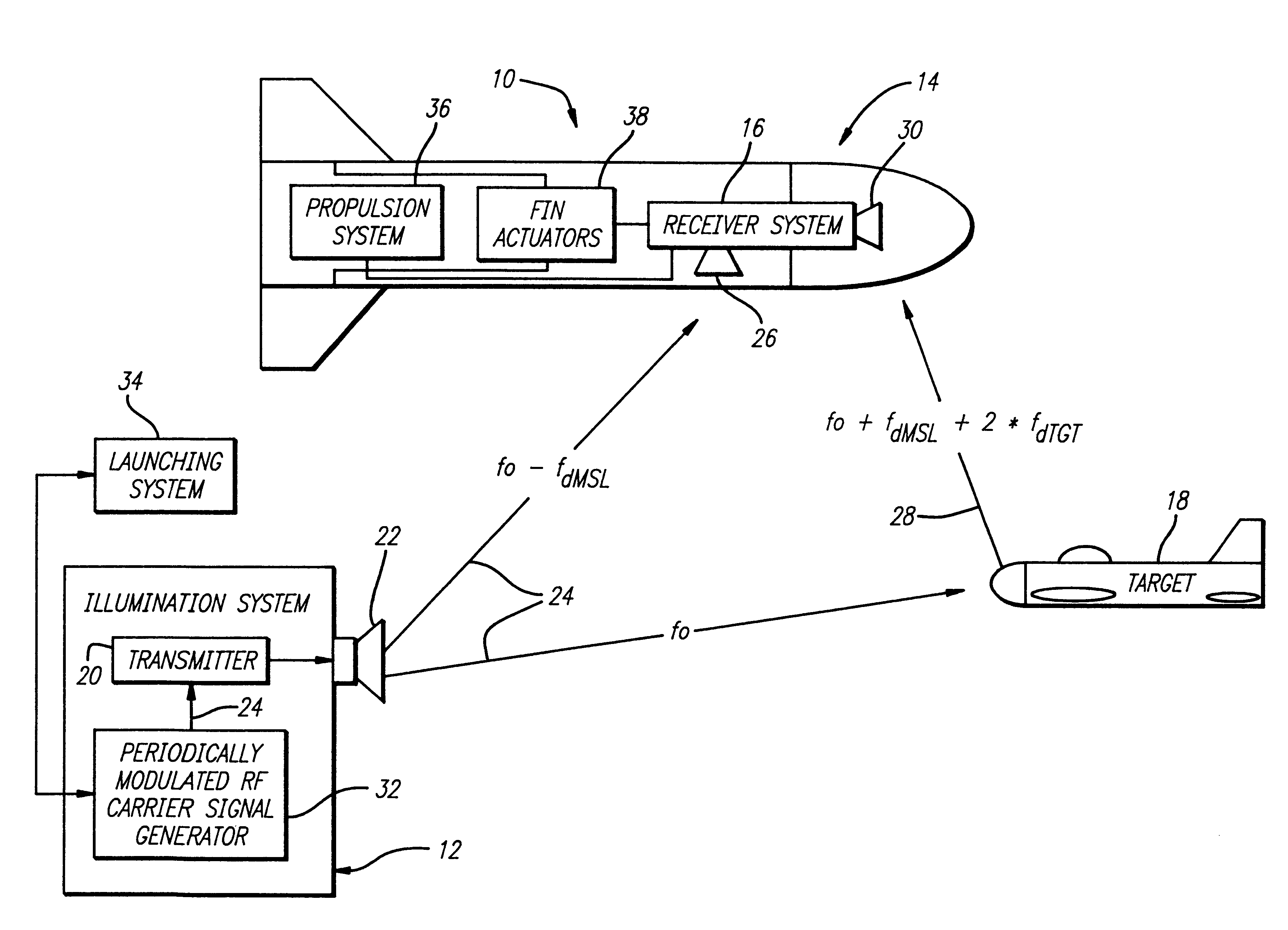
FIG. 1 is a diagram of the semi-active missile system 10 of the present invention showing an illumination system 12, a missile 14 with a receiver system 16, and a target 18. The illumination system 12 is connected to a missile launching system 34 and includes a periodically modulated radio frequency (RF) carrier signal generator 32 connected to a transmitter 20 that is connected to an antenna 22. The periodically modulated carrier signal generator 32 generates a periodically modulated carrier signal 24 that is transmitted by the illuminatio...


PUM


Abstract

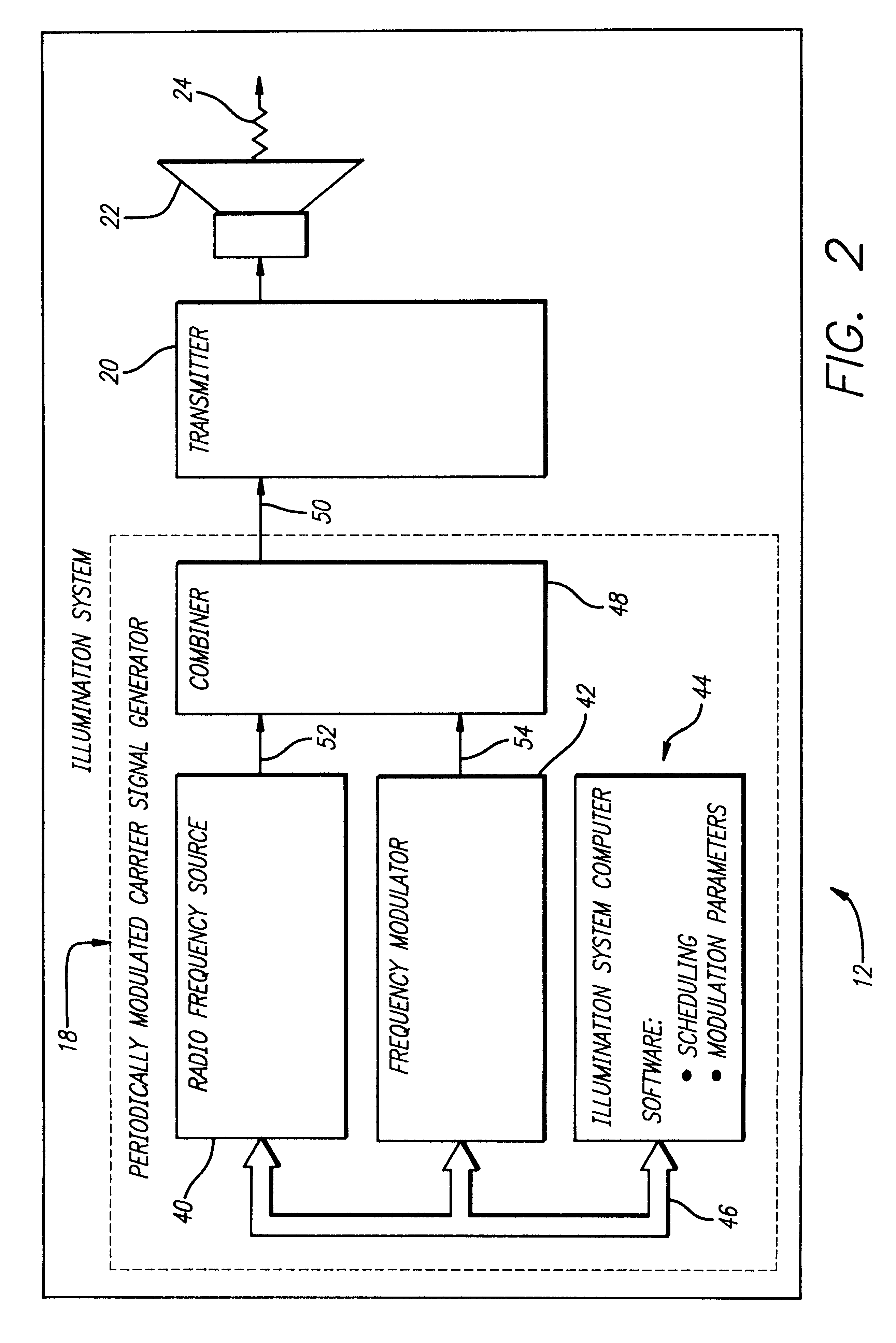
A system (10) for determining the range between a missile (14) and a target (18) adapted for use with a semi-active missile system. The system (10) includes a first circuit (12) for generating a periodic signal (24) that is periodically frequency modulated. A second circuit (16) determines a closing rate at which the missile 14 is approaching the target 18 via the periodic signal 24. A third circuit (16) determines a value containing information corresponding to the range and the closing rate via the periodic signal. A fourth circuit (16) determines the range from the closing rate and the value. In a specific embodiment, the first circuit (12) includes an illumination system (12). The illumination system (12) includes a periodically modulated carrier signal generator (32) that generates the periodic signal (24). The periodically modulated carrier signal generator (32) includes a frequency source, a frequency modulator, and an illumination system computer. The illumination system computer runs software for adjusting the modulation parameters of the frequency modulator. The second, third and fourth circuits (16) are included in a receiver system (16) onboard the missile (14). The receiver system (16) includes a front receiver located near the front of the missile and a rear receiver located near the rear of the missile (14). A receiver system computer runs software that implements the fourth circuit (16). The receiver system (16) includes a local oscillator for providing a reference frequency for the receiver system. The local oscillator derives the reference frequency from the periodic signal provided by the first circuit. In illustrative embodiment, the fourth circuit (16) runs computer software that subtracts the closing rate from the combination of closing rate and range and provides the range in response thereto.

Description

1. Field of InventionThis invention relates to missile guidance systems. Specifically, the present invention relates systems for determining missile closing rate and relative range with respect to a target.2. Description of the Related ArtMissiles are used in a variety of demanding applications ranging from explosives delivery to satellite launching applications. Such applications often require accurate target closing rate and closing distance information to make in-flight steering and arming adjustments.Missile guidance algorithms depend on accurate closing distance, i.e., range, and closing rate information to accurately time the activation of missile arming procedures and to successfully direct a missile to its target. Poor or corrupted missile closing rate and / or range information may cause premature missile detonation or missile targeting error.In active missile systems, a transmitter onboard the missile facilitates ranging, i.e., a determination of the distance between the mis...

Claims


Application Information

Patent Timeline
IPC IPC(8): F42C13/00F42C13/04G01S13/00F41G7/22F41G7/20
CPCF41G7/2266F41G7/2286F42C13/045G01S13/003
Inventor SHARKA, DAVIDMELTZER, HARVEY J.
Owner RAYTHEON CO
Learn More