

Reflector, reflective polarizing plate and reflective liquid crystal display
a technology of reflective polarizing plate and liquid crystal display, which is applied in the direction of mirrors, instruments, polarising elements, etc., can solve the problems of poor image visibility and tacky resin binder
- Summary
- Abstract
- Description
- Claims
- Application Information
AI Technical Summary
Benefits of technology
Problems solved by technology
Method used
Image

Examples
example 1
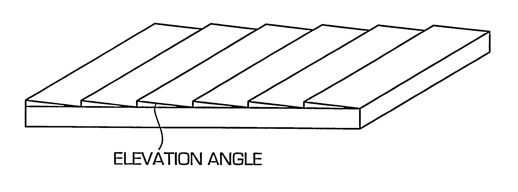
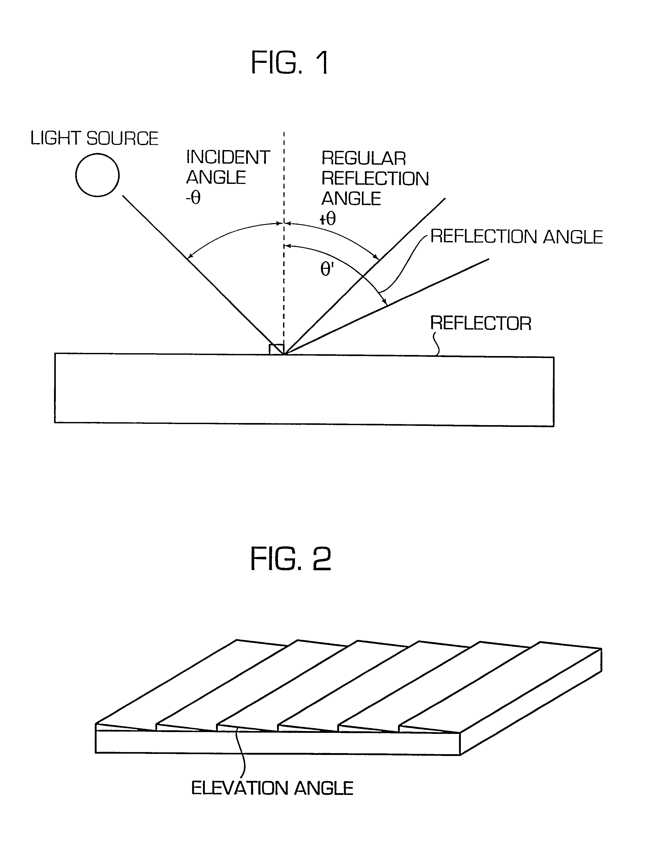
A reflector was produced by vapor depositing a film of aluminum (having an average thickness of 60 nm) by vacuum deposition on a plastic film (manufactured by Dainippon Printing Co., Ltd.), the surface of which had a saw-teeth shape such that triangular prisms are arranged in adjacent to each other in their ridge directions, as shown in FIG. 2. In the cross section of the prisms, an angle of elevation of each triangle was 7.5 degrees, and the vertical angle was 82.5 degrees. The pitch of the prisms was 200 .mu.m.
The center line average roughness (Ra) of the surface of the reflector was 533 nm.
This reflector was illuminated at an angle of 45 degrees from the vertical direction to the reflector surface, and a angle-dependency of the intensity of reflected light was measured. The results are shown in FIG. 10.
The angle at which the intensity of reflected light was maximized was +60 degrees from the vertical direction. The regular reflection angle was +45. Thus, the deviation of the form...
example 2
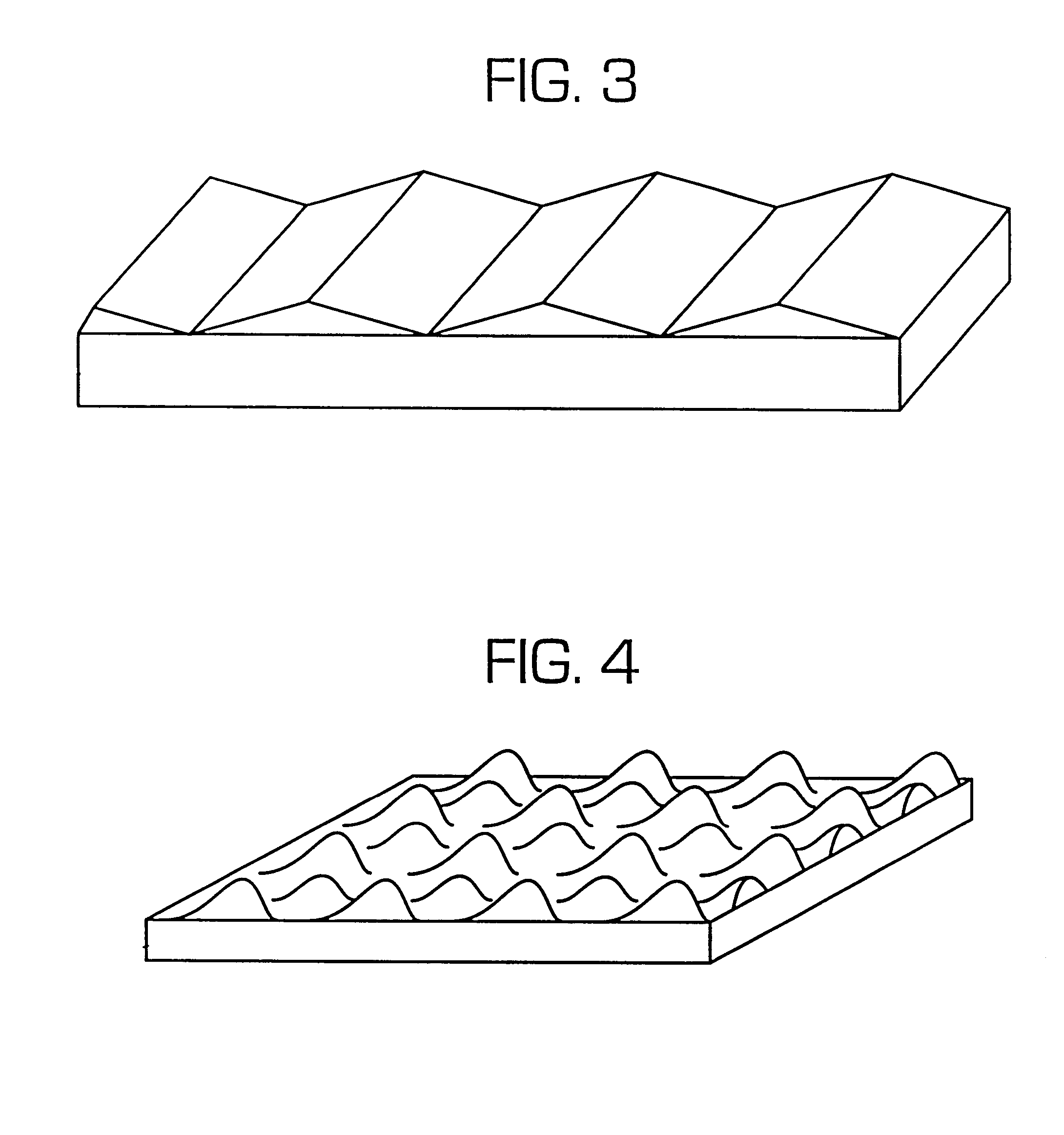
A reflector was produced by vapor depositing a film of aluminum (having an average thickness of 60 nm) by vacuum deposition on a plastic film (manufactured by Dainippon Printing Co., Ltd.), the surface of which had a saw-teeth shape such that triangular prisms are arranged in adjacent to each other in their ridge directions, as shown in FIG. 3. In the cross section of the prisms, both angles of elevation of each triangle were 7.5 degrees, and the vertical angle was 165 degrees. The pitch of the prisms was 200 .mu.m.
The center line average roughness (Ra) of the surface of the reflector was 389 nm.
This reflector was illuminated at an angle of 45 degrees from the vertical direction to the reflector surface, and an angle-dependency of the intensity of reflected light was measured. The results are shown in FIG. 11.
The angles at which the amount of reflected light was maximized were +30 and +60 degrees from the vertical direction. The regular reflection angle was +45 degrees. Thus, the de...
example 3
A reflector was produced by vapor depositing a film of aluminum by vacuum deposition on a plastic film having the surface structure consisting of quadrangular pyramids arranged with their bases being in contact with each other, the cross section of which in a plane which includes the center of the slope triangle and is vertical to the base planes of the pyramids was a saw-teeth shape such that triangles are linked, as shown in FIG. 9. In each cross sectional triangle of the pyramid, both angles of elevation of each triangle were 7.5 degrees, and the vertical angle was 165 degrees. The pitch of the prisms was 200 .mu.m.
When this reflector was illuminated at an angle of 45 degrees from the vertical direction to the reflector surface, the angles at which the intensity of reflected light was maximized were 30 and 60 degrees from the normal line, while the regular reflection angle was +45 degrees.
This reflector was laminated on a polarizing plate (an iodine base polarizing plate; SG manu...
PUM
 Abstract
Description
Claims
Application Information