Pipe clamp

Inactive Publication Date: 2001-03-27
TOGO SEISAKUSYO
View PDF12 Cites 71 Cited by
  • Summary
  • Abstract
  • Description
  • Claims
  • Application Information

AI Technical Summary

Benefits of technology

The present invention has been made in view of the foregoing, and an obj

Problems solved by technology

In use of the pipe clamp formed integrally of the resin as described above, however, the transfer of vibration is difficult to be prevent.
The integrating work i

Method used


Image

  • Pipe clamp
  • Pipe clamp
  • Pipe clamp

Examples


first embodiment

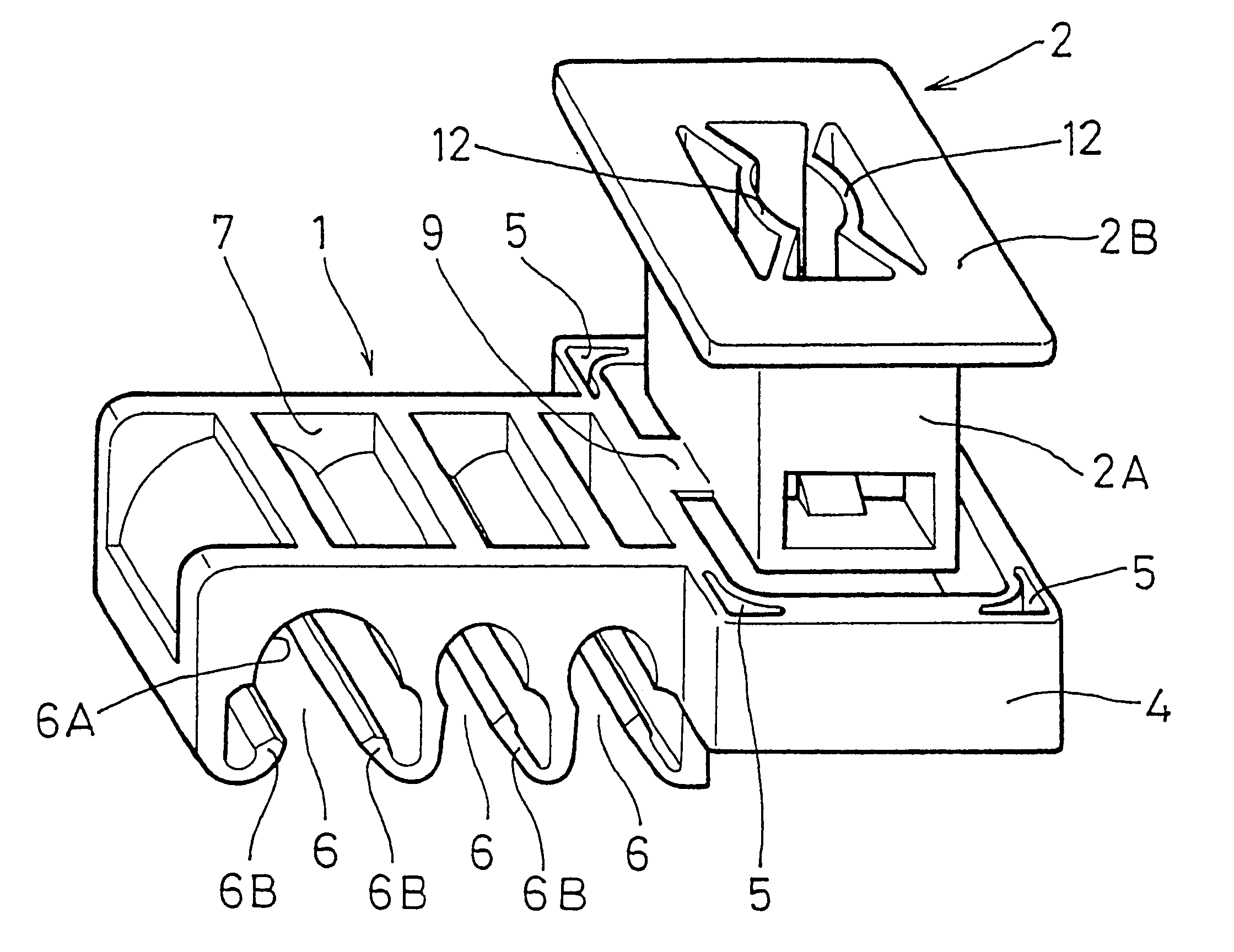
the present invention will be described with reference to FIGS. 1 to 7. In the first embodiment, the pipe clamp PC is used to fix automobile piping such as a brake fluid piping to a body panel B. The piping will hereinafter be referred to as "pipe P."

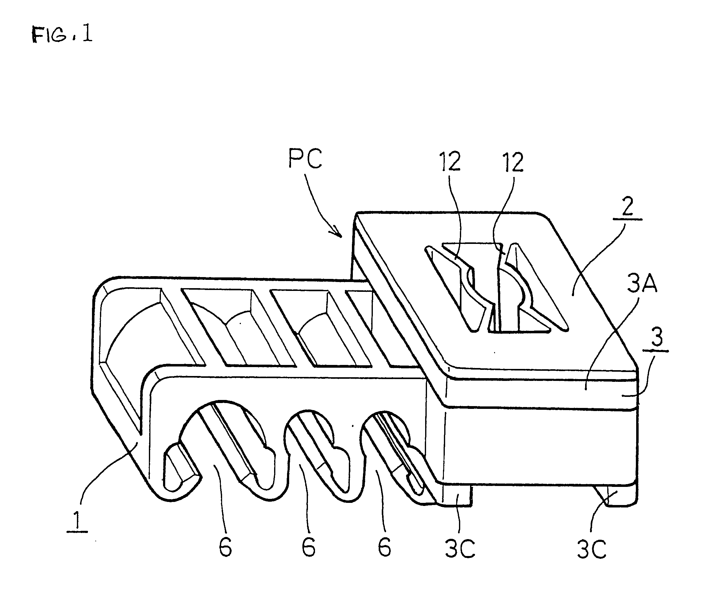
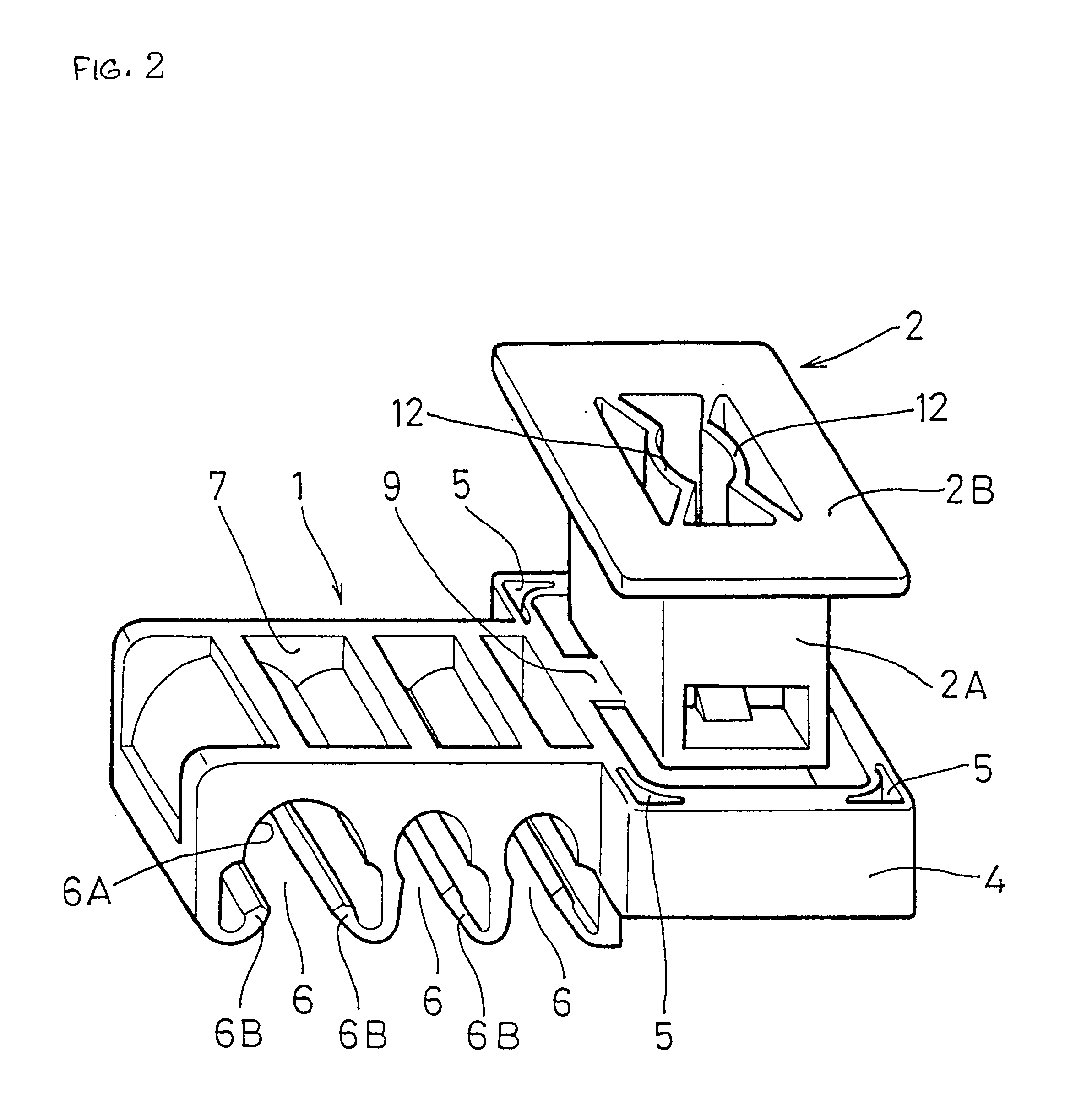
The pipe clamp PC of the first embodiment comprises a holding member 1 for holding a plurality of pipes P, a mounting member 2 provided for fixing the pipes P to the automobile body side, and a coupling member 3 for coupling the holding and mounting members together by insert molding to serve to absorb of vibration. The holding member 1 and the mounting member 2 are integrated before the forming of the coupling member 3 as shown in FIG. 2. The holding member 1 and the mounting member 2 are each formed of a hard synthetic resin such as polyacetal. The coupling member 3 is formed of a soft resin with elasticity, for example, an elastomer of the styrene-butylene system.

The holding member 1 will first be described. The holding member 1 is p...

third embodiment

The third embodiment is directed to a solution of the above-described problem. In the pipe clamp of the third embodiment, the holding member 31 comprises a first holding member 31A and a second holding member 31B each formed of a hard synthetic resin such as polyacetal and connected together by a collapsible connecting edge 52 for separation. The mounting member 33 is connected to the first holding member 31A by the connecting portion 34. However, the third embodiment differs from the foregoing embodiments in that a predetermined positional relation between the mounting member 33 and the first holding member 31A is maintained in the breaking of the connecting portions 34 without the movement of the mounting member.

The mounting member 33 will first be described. The mounting member 33 is formed of the same hard resin as the first and second holding members 31A and 31B into the shape of a square cylinder with upper and lower open ends. The mounting member 33 has a pair of visor edges ...


PUM


Abstract

A holding member (1) for holding a pipe (P), and a mounting member (2) for fixing the pipe (P) to a body panel (B) are previously connected together by a thin connecting portion (9). The holding member (1) and the mounting member (2) in the integrated state are set in a forming die. The connecting portion (9) is collapsed with the closing of such the die that the holding member (1) and the mounting member (2) are separated from each other. A coupling member (3) is formed in this state. Accordingly, the working efficiency can be improved as compared with the case where the holding member and the mounting member are individually set in the die. The holding member (1) and the mounting member (2) are coupled together by the coupling member (3). Since the coupling member (3) is formed of a rubber material, vibration caused in the pipe (P) can be prevented from being transferred to the body panel.

Description

BACKGROUND OF THE INVENTION1. Field of the InventionThis invention relates to pipe clamps for holding various types of pipes.2. Description of the Prior ArtVarious types of pipes are used in automobiles and resin holders called pipe clamps are conventionally used to fix the pipes to the automobile body side. The pipe clamps are usually formed integrally of a resin such as polypropylene. Pulsation of a fluid flowing through the pipe sometimes vibrates the pipe clamp. The vibration needs to be prevented from being transferred via the pipe clamp to the automobile body side. In use of the pipe clamp formed integrally of the resin as described above, however, the transfer of vibration is difficult to be prevent.The prior art has developed a pipe clamp in which a soft resin portion with the ability to absorb vibration is stacked on a pipe holding portion thereof so that the pipe overlaps the soft resin portion. However, since the pipe is held by the soft resin, a holding force against the...

Claims


Application Information

Patent Timeline
IPC IPC(8): F16L3/22F16B37/08F16B2/20F16L3/223
CPCF16B37/0842F16L3/223F16L55/035Y10S248/909F16B2/20
Inventor OI, SHIGEOMATSUNAGA, RYOSUKE
Owner TOGO SEISAKUSYO
Why Eureka
Try Eureka