Permanent magnet electric rotating machine and electromotive vehicle using permanent magnet electric rotating machine

a permanent magnet electric rotating machine and electric rotating machine technology, which is applied in the direction of dynamo-electric machines, magnetic circuit rotating parts, magnetic circuit shape/form/construction, etc., can solve the problems of permanent magnet peeling, inability to achieve stable operation of permanent magnet electric rotating machines, and inability to reduce cogging torque or torque pulsation

Inactive Publication Date: 2001-03-27
HITACHI LTD +1
View PDF15 Cites 136 Cited by
  • Summary
  • Abstract
  • Description
  • Claims
  • Application Information

AI Technical Summary

Problems solved by technology

However, in the above stated surface magnet structure permanent magnet electric rotating machine, during a high speed rotation there is a possibility of the permanent magnet peeling off due to centrifugal force.
However, in the above stated prior art, there is a problem in which an obtaining of a reluctant torque by auxiliary magnetic poles and a reduction in a cogging torque or a torque pulsation are not incompatible.
This torque pulsation obstructs a smooth rotation of the rotor, thus causing a problem in which a stable operation of the permanent magnet electric rotating machine cannot be obtained.
However, the above stated space or the fill-up member does not work as the auxiliary magnetic pole, therefore the reluctant torque can not be obtained.
However, due to the provision of the above described magnetic gap at the peripheral direction end portion of the permanent magnet, there is a possibility that the positioning of the permanent magnet becomes unstable during the high speed rotation, etc.

Method used


Image

  • Permanent magnet electric rotating machine and electromotive vehicle using permanent magnet electric rotating machine
  • Permanent magnet electric rotating machine and electromotive vehicle using permanent magnet electric rotating machine
  • Permanent magnet electric rotating machine and electromotive vehicle using permanent magnet electric rotating machine

Examples


Embodiment Construction

Hereinafter, one embodiment of a permanent magnet electric rotating machine according to the present invention and an electromotive vehicle using a permanent magnet electric rotating machine according to the present invention will be explained in detail referring to figures.

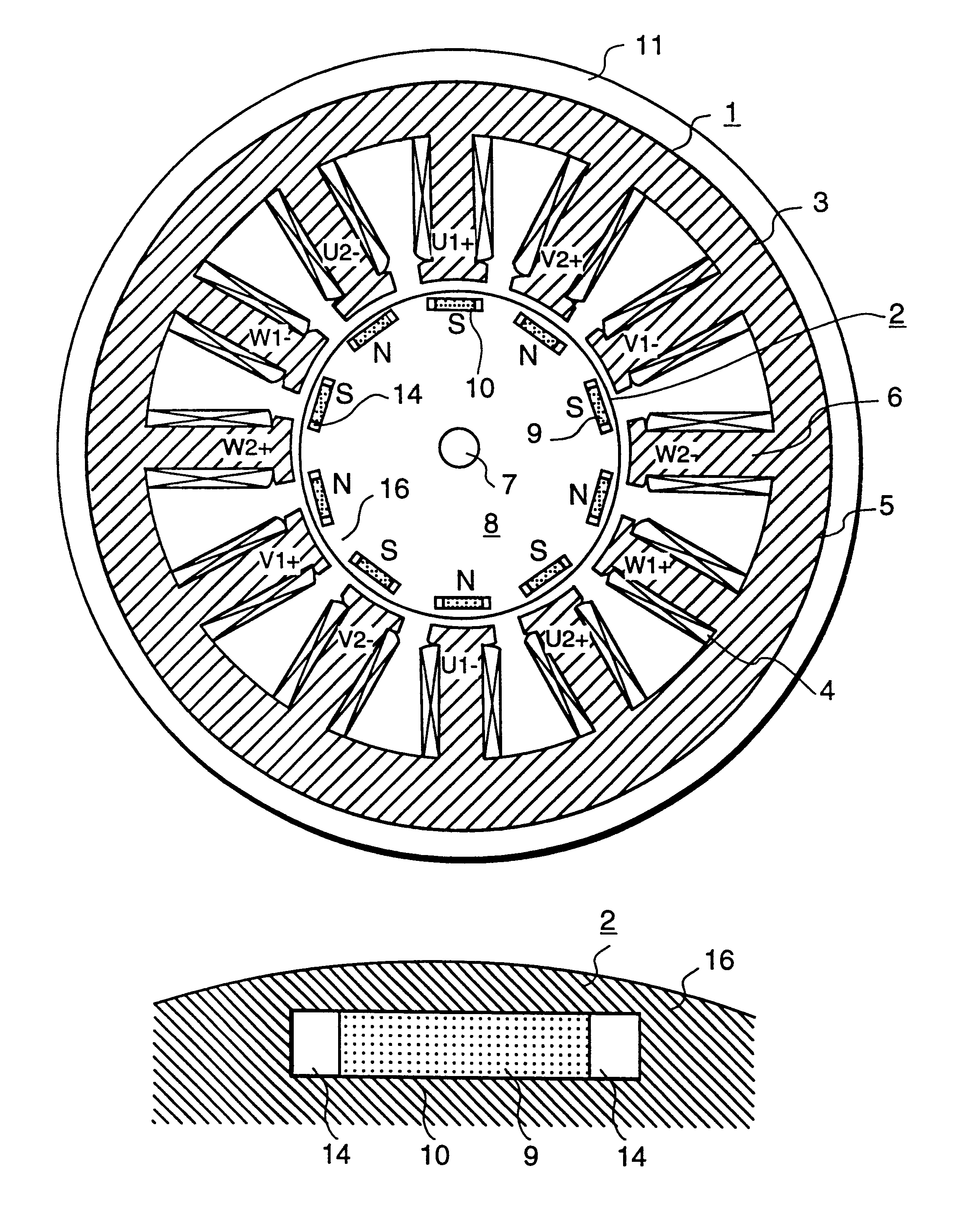
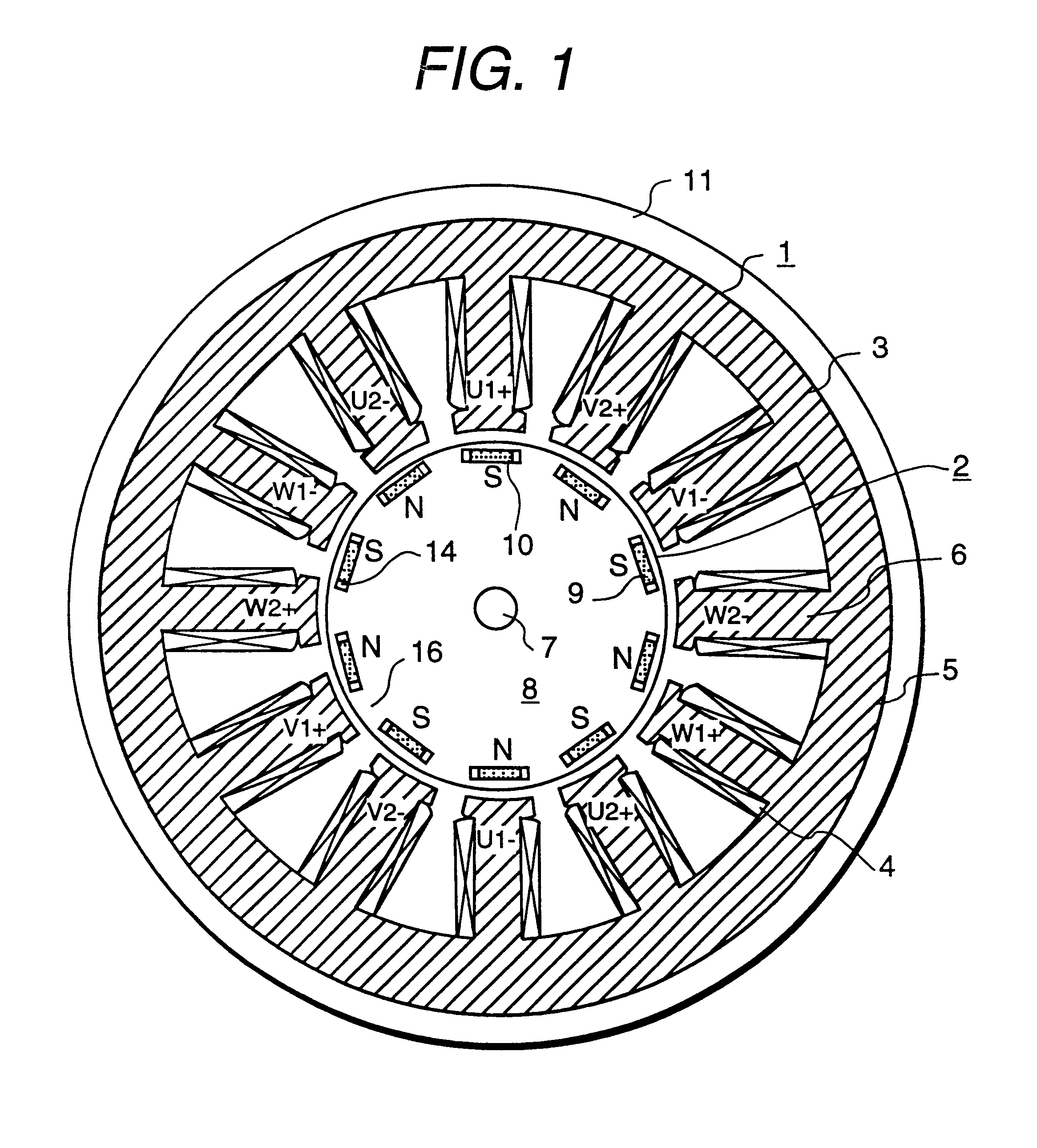
FIG. 1 is a cross-sectional view of the periphery of one embodiment of a permanent magnet electric rotating machine according to the present invention having an inner rotor and a concentrated winding stator structure.

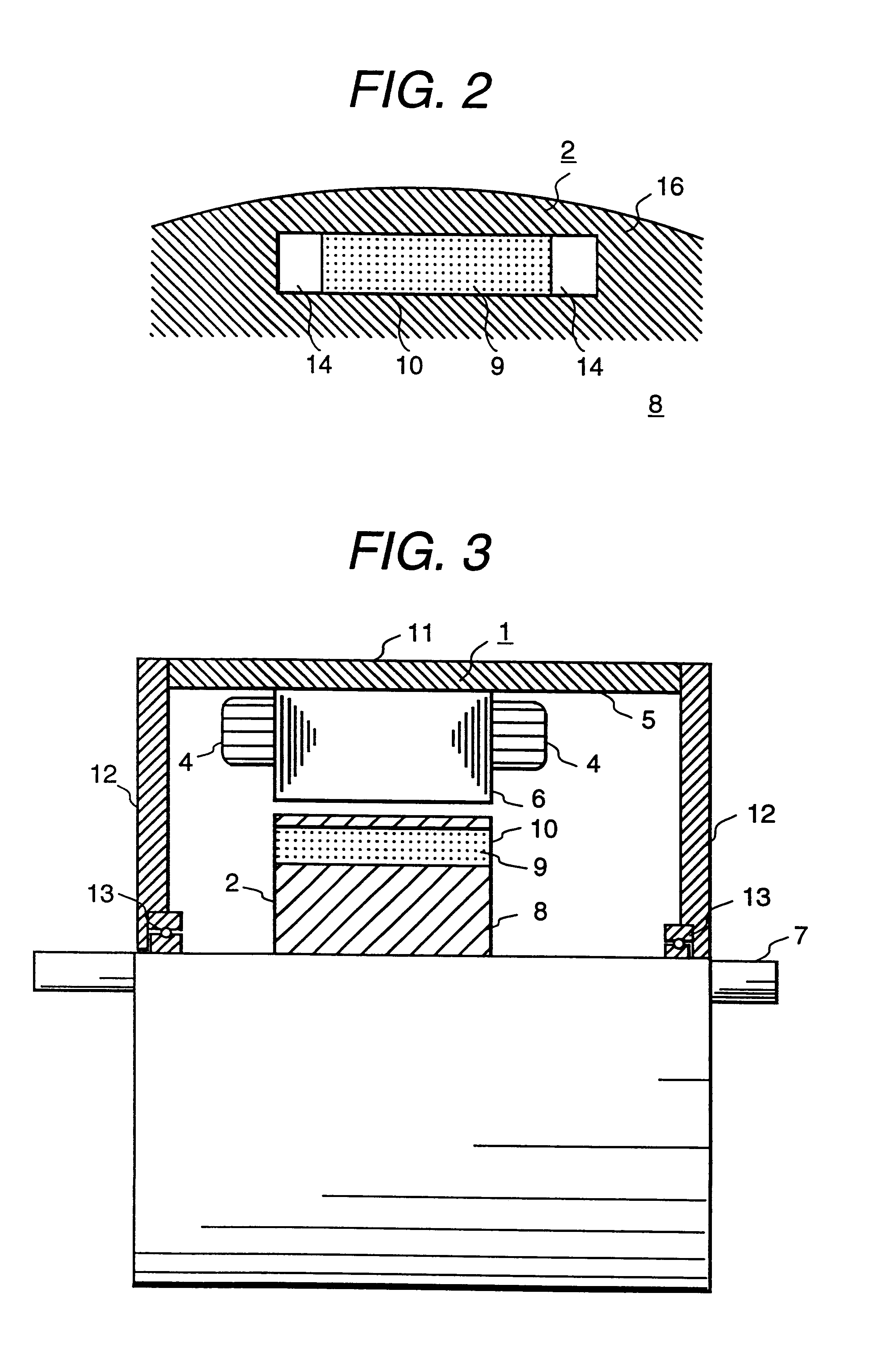
A permanent magnet electric rotating machine is constituted by a stator 1 and a rotor 2. The stator 1 and the rotor 2 are arranged with a rotation air gap formed between one another as shown in FIG. 1.

The stator 1 comprises a stator iron core 3 and a stator winding 4. The stator iron core 3 comprises a core portion 5 and a stator salient pole portion 6. In the core portion 5, a magnetic circuit is formed so to pass a magnetic flux to the stator salient pole portion 6. In this stator salient pole port...


PUM


Abstract

A magnetic gap is provided between a permanent magnet of a rotor and an auxiliary magnetic pole portion which is arranged adjacent to the permanent magnet in a peripheral direction. A gradual change in a magnetic flux density distribution of a surface of the rotor is obtained and a cogging torque and a torque pulsation are restrained. By obtaining a reluctance torque according to the auxiliary magnetic pole, a permanent magnet electric rotating machine in which the cogging torque and the torque pulsation are restrained can be obtained and further an electromotive vehicle having the permanent magnet electric rotating machine can be provided.

Description

1. Technical FieldThe present invention relates to a permanent magnet electric rotating machine and an electromotive vehicle using a permanent magnet electric rotating machine and in particularly to a permanent magnet electric rotating machine in which permanent magnets are used as a magnetic flux generating means and an electromotive vehicle such as an electric vehicle which uses the permanent magnet electric rotating machine.2. Prior ArtUp to now as one kind of an electric rotating machine, a permanent magnet electric rotating machine has been used, in which permanent magnets of the permanent magnet electric rotating machine are used as a magnetic field generating means for a rotor.As a conventional permanent magnet electric rotating machine, there is a known surface magnet structure permanent magnet electric rotating machine, wherein plural permanent magnets of the permanent magnet electric rotating machine are arranged in parallel and fixed on a surface of a rotor and further ad...

Claims


Application Information

Patent Timeline
Patent Type & Authority Patents(United States)
IPC IPC(8): H02K1/27
CPCH02K1/276H02K29/03
Inventor TAJIMA, FUMIOMATSUNOBU, YUTAKAKAWAMATA, SHOUICHISHIBUKAWA, SUETAROKOIZUMI, OSAMUODA, KEIJI
Owner HITACHI LTD
Why Eureka
Try Eureka