
Microtome

a microtome and microtome technology, applied in the field of microtomes, can solve the problems of limiting cutting frequency, difficult to remove the microtome sections, and obvious disadvantages,

Inactive Publication Date: 2001-04-03
MICROM INT
View PDF15 Cites 29 Cited by
  • Summary
  • Abstract
  • Description
  • Claims
  • Application Information

AI Technical Summary

Benefits of technology

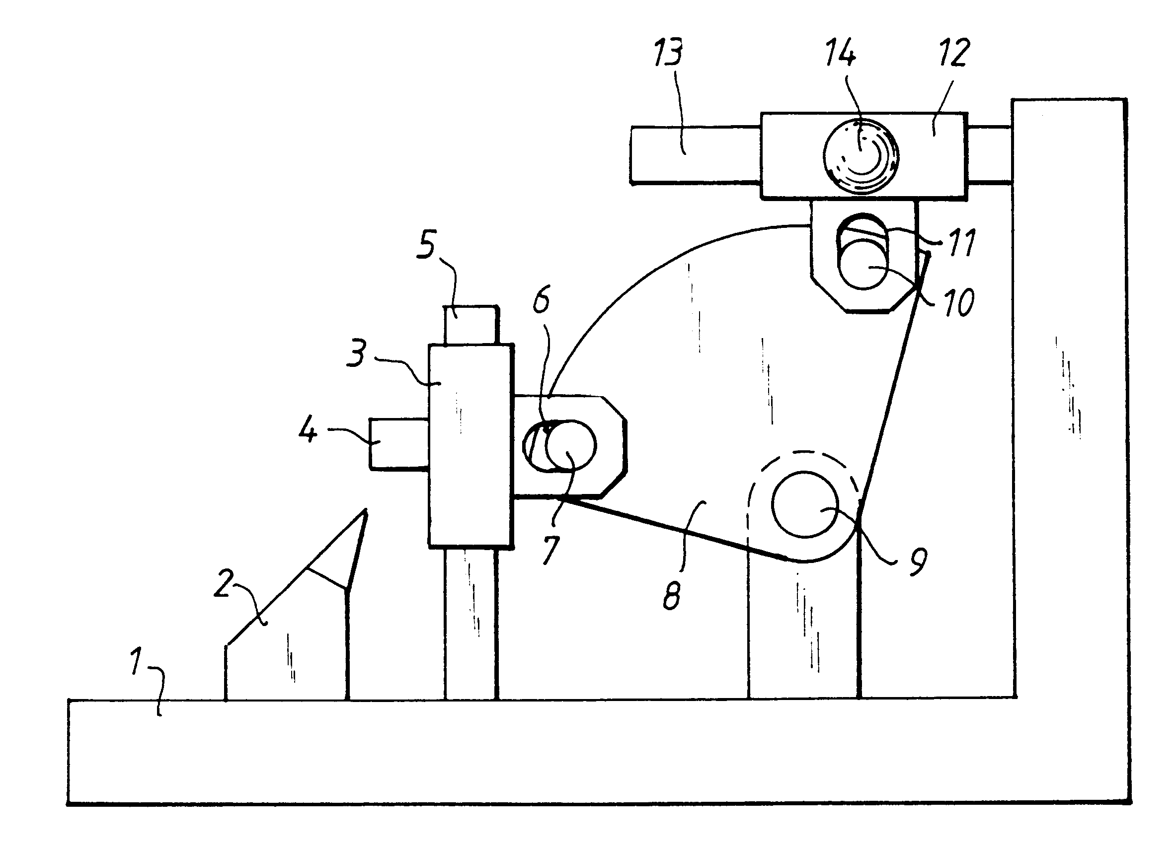
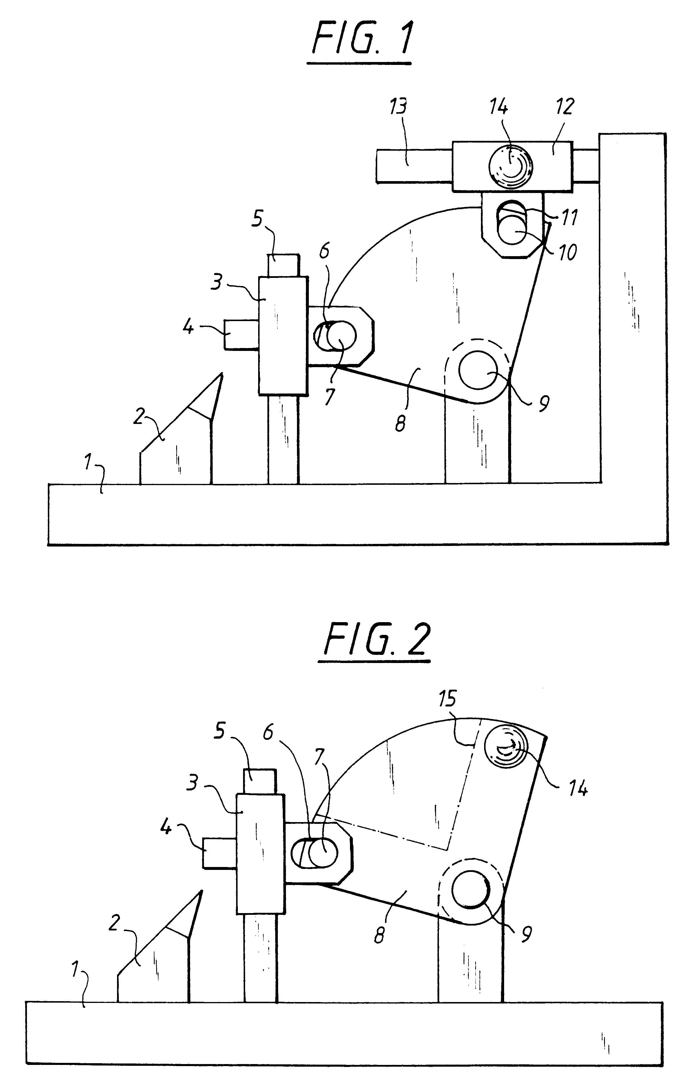
By the deflection of the paths of motion between the hand drive and the sample holder, the motion of the hand drive can take place substantially horizontally forward and backward of the microtome (push and pull motion by the operator), which is considered to be particularly favorable from the ergonomic viewpoint, and can be converted into a motion of the sample carrier, substantially perpendicular to the motion of the hand drive. The cutting motion can thus take place in a substantially vertical direction, so that the sections which are produced can be removed or washed away from the inclined back surface of the cutting knife or knife carrier.

Problems solved by technology

On the other hand, it is a disadvantage that the removal of the microtome sections is quite complicated.
This disadvantage clearly becomes manifest in the latest slide microtomes, which have an electrical drive of the sample feed, such as that offered by the Applicant under the designation "OHM 440".
However, it has been found that the time required for removal of sections limits the cutting frequency.
However, such rotary microtomes have the disadvantage that the rotary motion of the handle is quite tiring.
However, the motors which would be required for this would nearly double the price of the microtome.

Method used


Image

  • Microtome
  • Microtome
  • Microtome

Examples


Embodiment Construction

The embodiment according to FIG. 1 contains a baseplate (1), on which the knife carrier (2) is received in the forward region, facing the user, and is movable back and forth horizontally, that is, in the direction of the baseplate (1). The sample carrier (3), with a sample (4), is received, vertically movable, on a guide (5) which is oriented perpendicularly to the baseplate (1). The guided slide of the sample carrier (3) has a groove (6) in which there engages a pin (7) of a plate (8) of circular segment shape. The circular segment plate (8) is mounted for rotation about a rotation axis (9). The plate (8) has a second pin (10), spaced apart from the first pin (7), and engaging in the groove (11) of a horizontally guided slide (12). A horizontal guideway (13) is connected to the baseplate (1) of the microtome in order to guide the slide (12). A handle (14) for the manual operation of the cutting motion is provided on the slide (12).

The circular segment plate (8) with the two pins (7...


PUM

PropertyMeasurementUnit
angleaaaaaaaaaa
shapeaaaaaaaaaa
massaaaaaaaaaa

Abstract

The microtome has a sample carrier movable along a first linear guide and a hand drive movable along a substantially linear path of motion that is substantially perpendicular to the direction of motion of the sample carrier. A deflecting device is provided to deflect the motion of the hand drive into a motion in the direction of the linear guide of the sample carrier. By deflection of the paths of motion between the hand drive and the sample holder, the motion of the hand drive can take place substantially horizontally forward and backward and convert the motion of the hand drive into a motion of the sample carrier which is substantially perpendicular to the motion of the hand drive. The cutting motion takes place in a substantially vertical direction, so that the sections can be removed or washed away from the inclined back surface of the cutting knife or knife carrier.

Description

1. Field of the InventionThe invention relates to a microtome for the production of histological sections, particularly of plant and animal tissues, which are intended for microscopic inspection.2. Discussion of Prior ArtSo-called slide microtomes are known from the Soviet Inventor's Certificate SU-783626 or from the Applicant's EP-A1 0 416 354, and have a baseplate with an object carrier and in addition substantially horizontal guides. A knife holder is movably received in the horizontal guides and is provided with a handle. The knife holder moves back and forth, linearly and horizontally, and its motion is coupled with a feed drive of the sample carrier.Slide microtomes are distinguished by their simple construction and the consequent low price. Moreover they are distinguished, as long as the user follows a sufficient routine, by operation which is not tedious. On the other hand, it is a disadvantage that the removal of the microtome sections is quite complicated. This disadvantag...

Claims


Application Information

Patent Timeline
Patent Type & Authority Patents(United States)
IPC IPC(8): B26D7/06G01N1/04G01N1/06
CPCB26D7/0616G01N1/06Y10T83/6499
Inventor IZVOZTCHIKOV, ILIAHEID, HANS
Owner MICROM INT
Learn More