Ball rebound device

a rebound device and ball technology, applied in the field of improved recreational practice devices, can solve the problems of limited ability to efficiently rebound balls, limited ability to rebound balls with appreciable speed, and the same severe limitation, so as to increase speed and distance, efficiently utilize kinetic energy, and increase the effect of speed and distan

Inactive Publication Date: 2001-04-03
WARNICK BRUCE D
View PDF8 Cites 33 Cited by
  • Summary
  • Abstract
  • Description
  • Claims
  • Application Information

AI Technical Summary

Benefits of technology

Accordingly, my ball rebound device has several objects and advantages:
It is an object of my ball rebound device to rebound a large playground ball such as a soccer ball, basketball, or kick ball propelled there-against by the user with increased speed and distance to enable the user to more quickly increase his ball handling skills. It is further an object of my ball rebound device to more efficiently utilize the kinetic energy of a playground size ball which strikes the device, so that the ball is rebounded from the device with a velocity not appreciably less than the velocity of the ball before impact, thereby providing the user with a more fruitful practice session with minimal effort.
My ball rebound device does not use a net, rigid rebound panel, nor a modified trampoline. My ball rebound device is able to rebound a playground size ball such as a soccer ball, basketball, or kick ball with higher speed and greater distance by the use of monofilament nylon cords which are individually strung taut within a frame. The cords are similar to tennis racket string. Each cord is preferably strung individually back and forth within the frame in a basket weave fashion--as a tennis racket is strung, enabling the device to convert a high percentage of the kinetic energy of the ball to a powerful rebound back to the user. By rebounding the ball back at a higher speed and for a greater distance, the user is provided with more challenging practice sessions in the skills of kicking, throwing, passing

Problems solved by technology

The rebound surface provided by this class of devices has a limited capacity for rebounding a ball with appreciable speed.
No matter how taut a net is stretched, it still has a limited ability to efficiently rebound a ball due to its inherent design and construction.
However, they all face the same severe limitation--they absorb and dissipate an appreciable amount of energy from the ball instead of efficiently storing and then re-administering the energy to the ball.
However, since the panels are solid and do not react at all in response to the ball, the rebound velocity depends largely upon the compression of the ball upon impact with the panel and the inherent tendency of the ball to quickly achieve the expanded condition.
These devices may also contain other parts such as fasteners connecting the springs to the panel and a frame which inherently introduce undesirable frictio

Method used


Image

  • Ball rebound device
  • Ball rebound device
  • Ball rebound device

Examples


first embodiment

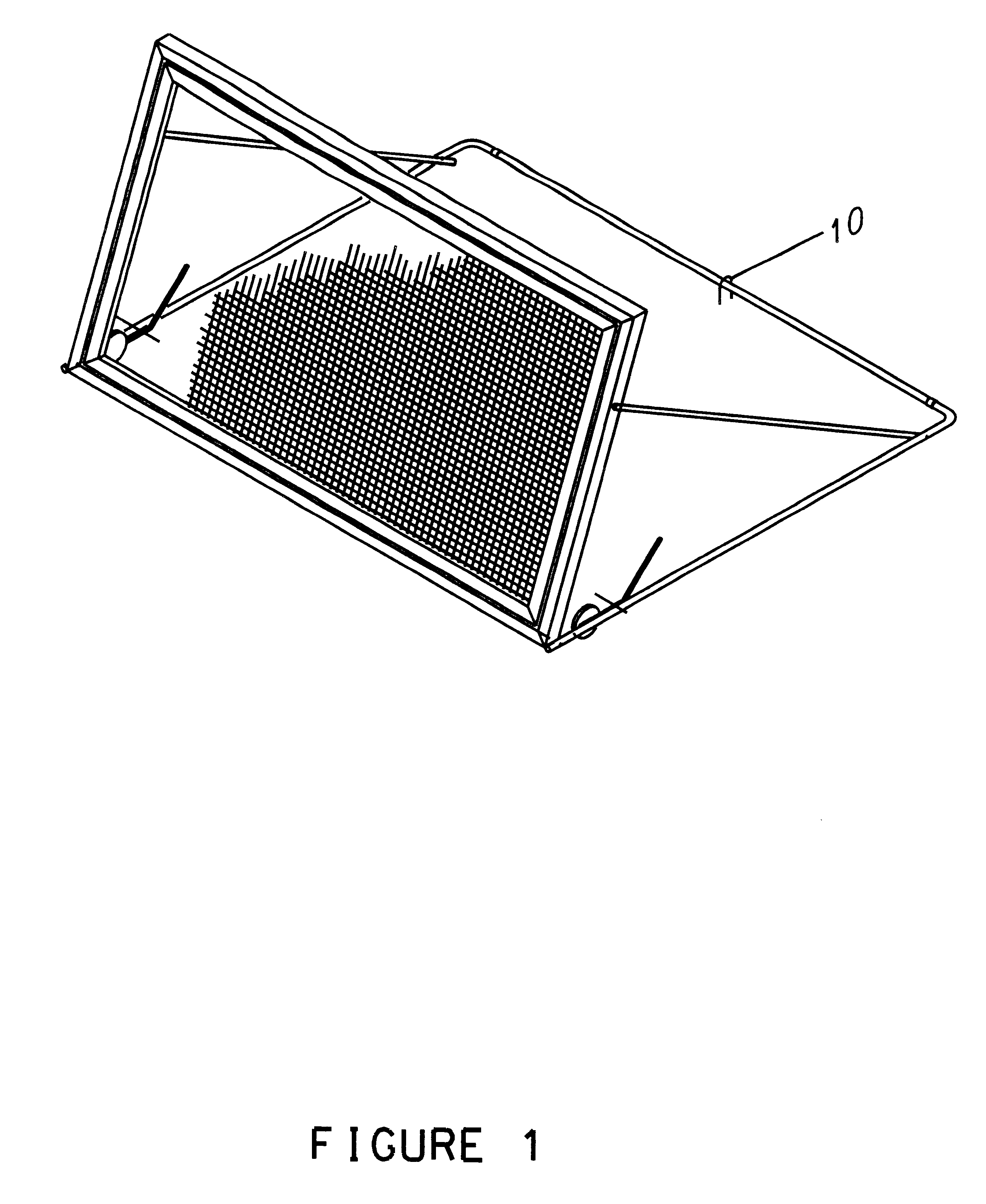
My rebound device is intended to be used with a playground type of ball (eg. soccer ball, kick ball, or basketball) which is relatively large in diameter (eg. at least eight inches in diameter), round, and inflated such that when it is propelled against a surface, it will compress and then suddenly return to its pre-compressed condition upon rebound from the surface. FIG. 1 shows a perspective view of a basic version of my ball rebound device. My ball rebound device has three major embodiments. The first embodiment consists of the frame assembly, the cord assembly, the support structure assembly, and the roller assembly.

Frame Assembly

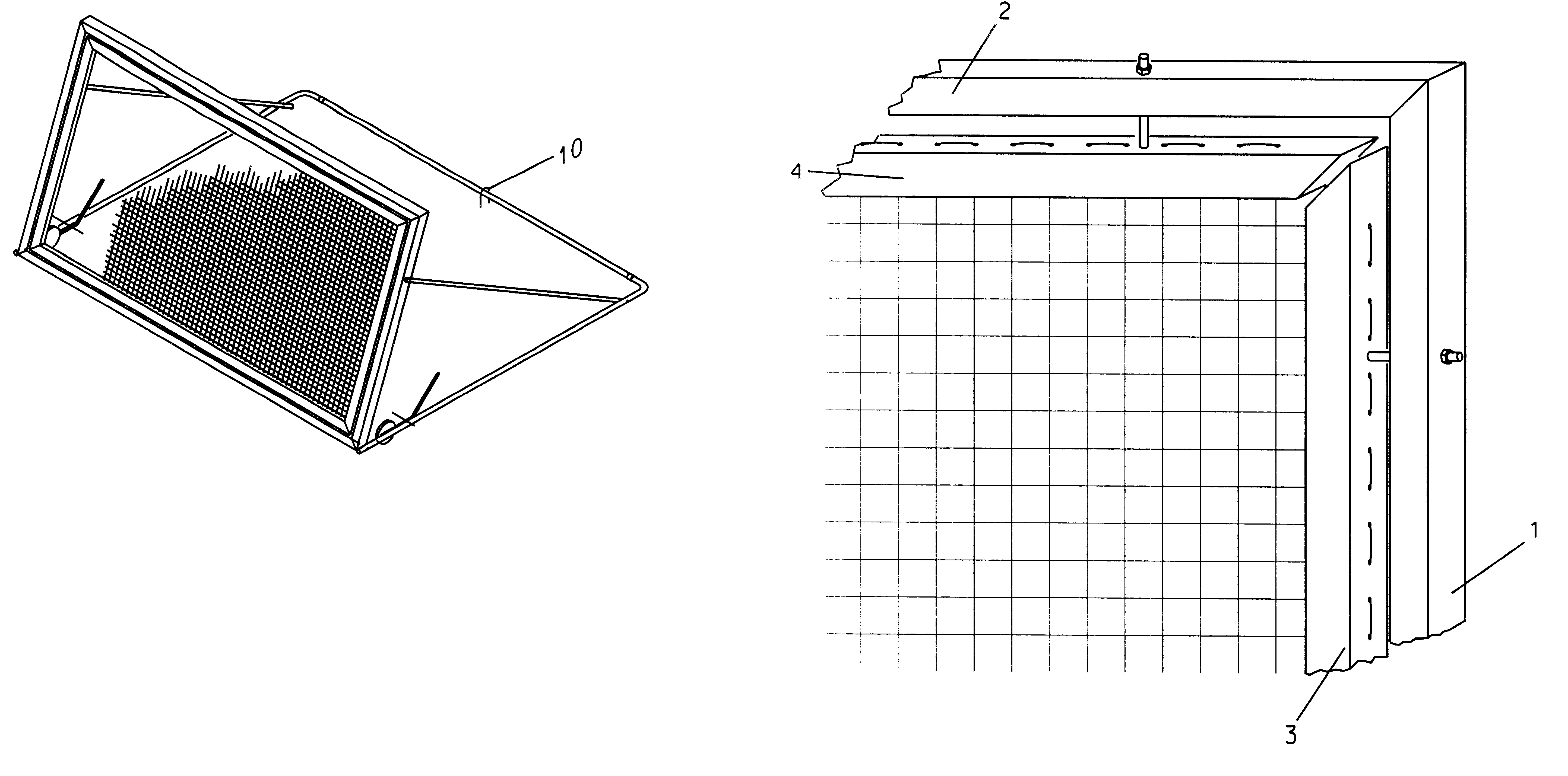
The Frame Assembly shown in FIG. 2, has two sub-components: the rigid structural members--items #1 and #2, and the adjustable tension members--items #3 and #4.

The rigid structural members provide the overall strength for the frame assembly. They consist of four angle iron or aluminum structural shapes; two of which are vertical members on each side--ite...

third embodiment

In the device shown in FIG. 1b, the support structure assembly has been eliminated to allow the frame assembly to be temporarily strapped to an existing soccer goal. In this embodiment, the frame assembly is identical to either of the two frame assembly embodiments described above. Once the frame assembly has been propped up against an existing goal, a set of four or six straps are strapped around the frame assembly and goal post to keep the frame assembly snug in a rigid condition against the goal so that the frame assembly is rigidly supported relative to the ground or other underlying support surface.

OPERATION OF BALL REBOUND DEVICE

The purpose of my ball rebound device is to enable the user to quickly increase his ball handling skills. The operation of this device will consist of many different types of practice sessions with users of varied skill levels, using any playground type ball such as a soccer ball, basketball, or a kick ball.

As a ball impacts the impact surface of the c...

embodiment 3

There are three basic embodiments to this ball rebound device: embodiments 1 and 2 operate in the same manner. Embodiment 3 which consists of a frame assembly and a cord assembly only, must be attached to a separate support structure such as the posts of an existing soccer goal to establish a rigid mounting.

Setup

The first two embodiments contain their own support structure. This allows the device to be oriented in many angular orientations for a more versatile practice session. It is wise to first stake the support assembly to the ground with one or two 1 / 2".times.18" rods bent in a U-fashion as shown in FIG. 1, item #10. This will ensure the device is stable and ready for rugged use. The user has at least two orientations of the frame from which to choose. A novice soccer user may choose to orient the frame in a reclining position as shown in FIG. 1c. The user would pull the clevis locking pins out of each of the adjustment mechanisms as shown in FIG. 4d and allow the frame to recl...


PUM


Abstract

An improved ball rebound device which will deliver a playground type ball such as a soccer ball, basketball, or kick ball which is propelled against the device, back to the user with surprising speed and distance. This ball rebound device utilizes a series of monofilament nylon elastic cords which are independently stung back and forth in a basket-weave fashion within a rectangular frame as a tennis racket is strung. This enables the device to more efficiently convert the kinetic energy of the ball into a powerful rebound back to the user. One embodiment of the device has within its frame the capability for adjustment of the tension of the cords to keep them operating at the desired tension. Another embodiment of the device has the capability for its frame to be adjustably oriented at various angles to the user to better suit the individual practice needs of the user.

Description

1. Field of InventionThis device is an improved recreational practice device which will rebound a playground size ball such as a soccer ball, kick ball, or a basketball which has been propelled against the device.2. Discussion of Prior ArtThere have been many ball rebound devices previously patented which attempt to rebound a ball to the user who tosses or kicks a ball to the device. These devices may be each grouped into one of the following four categories. Reference the applicable patents in each category:1) Pre-Woven fabric or net stretched taut within a frame,2) Rigid rebound panel,3) Rigid rebound panel with springs, 45537514) Modified trampoline--stretched fabric or net within a spring assisted frame, 4119311 50076381) Pre-Woven fabric or net stretched taut within a frame: These devices rebound a ball which has been tossed, kicked or otherwise propelled to it by a simple pre-woven fabric or net which has been stretched across a frame. The rebound surface provided by this clas...

Claims


Application Information

Patent Timeline
IPC IPC(8): A63B63/00A63B69/00A63B63/06
CPCA63B63/00A63B69/0097
Inventor WARNICK, BRUCE D.
Owner WARNICK BRUCE D
Why Eureka
Try Eureka