
Two stage power converter with interleaved buck regulators

Inactive Publication Date: 2001-04-03
COMM & POWER IND
View PDF10 Cites 103 Cited by
  • Summary
  • Abstract
  • Description
  • Claims
  • Application Information

AI Technical Summary

Problems solved by technology

On the other hand, the higher switching frequency reduces the efficiency of the power converter.
Higher switching frequencies at switch 20 generally result in greater power loss and require more expensive switching components.
Also, higher currents at inductor 30 generally require more expensive inductor components.

Method used


Image

  • Two stage power converter with interleaved buck regulators
  • Two stage power converter with interleaved buck regulators
  • Two stage power converter with interleaved buck regulators

Examples


Embodiment Construction

Those of ordinary skill in the art will realize that the following description of the present invention is illustrative only and not in any way limiting. Other embodiments of the invention will readily suggest themselves to such skilled persons having the benefit of this disclosure.

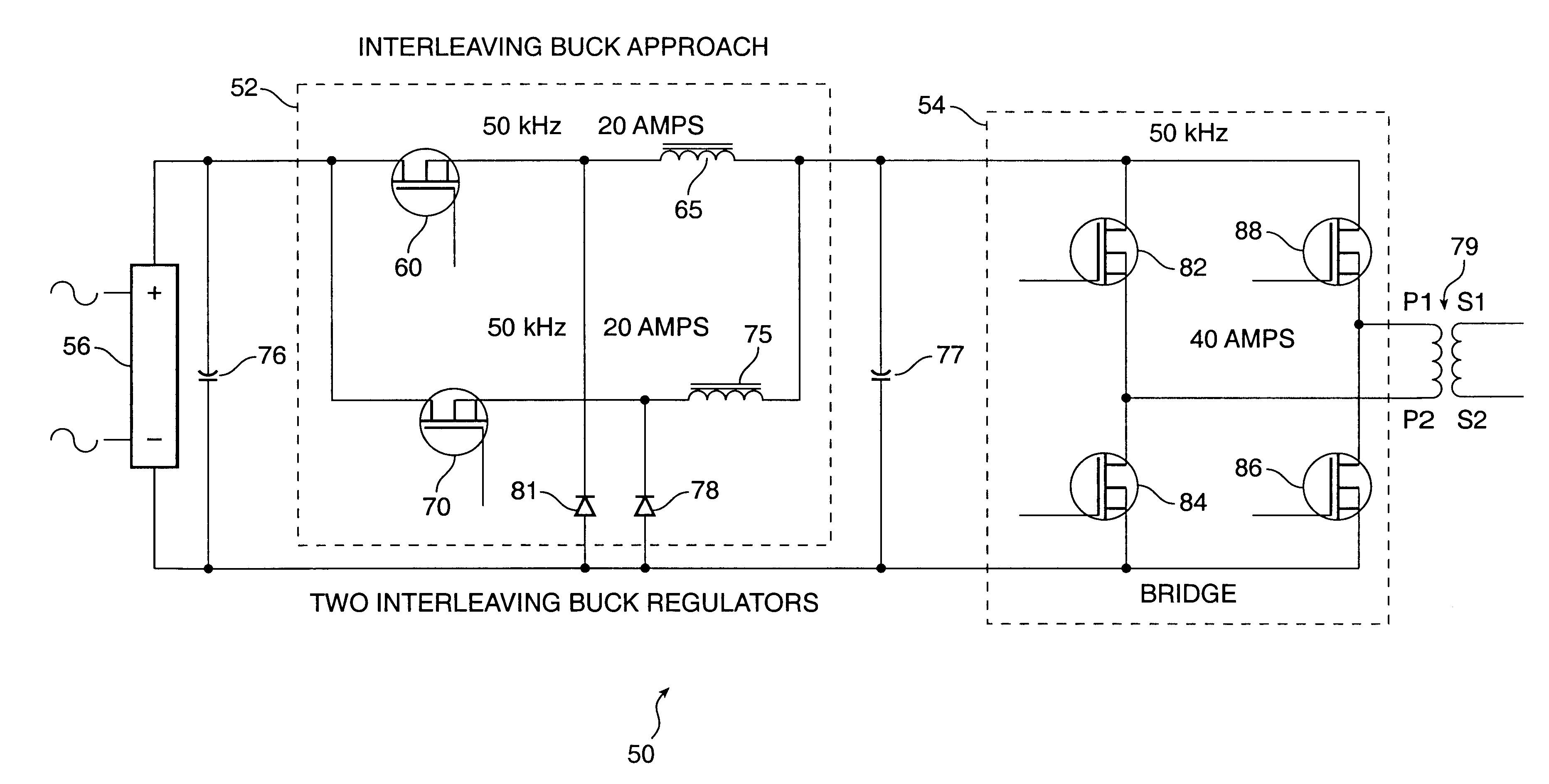
FIG. 3 is a schematic diagram of a two-stage power converter in accordance with a specific embodiment of the present invention. The converter 50 includes a buck regulator stage 52 and a bridge stage 54. By way of example, the converter produces a 50 KHz AC current. The converter operates as follows. A three-phase power source (e.g., 208 volts at 60 hertz) is applied to rectifier 56. Unregulated rectified DC power is applied to the buck regulator stage 52, which includes two interleaved buck regulators. One buck regulator comprises switch 60 and inductor 65. The other buck regulator comprises switch 70 and inductor 75. The switches comprise transistors. The buck regulator stage 52 produces regulated DC cur...


PUM


Abstract

A two-stage high power converter produces a highly regulated DC voltage from unregulated DC input. The first stage, having a plurality of interleaved buck regulators connected in parallel, converts unregulated DC voltage into regulated DC current. The second stage comprises a bridge for receiving the regulated current from the first stage, and converting it into AC voltage, which is in turn applied a step-up transformer. The secondary voltage of the transformer is rectified and filtered to produce low noise DC voltage. A method of converting unregulated DC voltage into regulated DC voltage comprises paralleling a plurality of interleaved buck regulators, where each of the buck regulators includes a switch. Each of the switches is controlled to operate at the same set frequency equal to two times the bridge operating frequency divided by the number of interleaved buck regulators. The combined current from interleaved buck regulators is fed to the bridge.

Description

1. Field of the InventionThe present invention relates to power supplies. More particularly, the present invention relates to high voltage low ripple power converters.2. Background ArtIn certain applications requiring a high voltage power source, it is desirable that the power source is substantially free of ripple effects. One known method of generating regulated high DC voltage at high power level involves rectifying an AC power source (e.g., 208 VAC, 60 Hz) and then converting the rectified DC voltage into high voltage using a high frequency switching converter. In such a scheme, the low frequency ripple components, mainly the line harmonics, are attenuated by a voltage feedback loop, whereas the high frequency components, produced by the switching converter, are greatly reduced by an LC output filter. Increasing the switching frequency makes the filtering easier--the feedback loop gain can be increased which improves input ripple rejection, and the low pass filter (removing swit...

Claims


Application Information

Patent Timeline
IPC IPC(8): H02M3/04H02M3/158
CPCH02M3/1584H02M2001/007H02M1/007
Inventor GOLUSZEK, DANIEL
Owner COMM & POWER IND
Features
  • Generate Ideas
  • Intellectual Property
  • Life Sciences
  • Materials
  • Tech Scout
  • Unparalleled Data Quality
  • Higher Quality Content
  • 60% Fewer Hallucinations
Learn More