Check patentability & draft patents in minutes with Patsnap Eureka AI!

Vibration isolator

a technology of vibration isolator and isolator body, which is applied in the direction of machine supports, shock absorbers, jet propulsion mountings, etc., can solve the problems of complex stopper structure and imposed design limitations

Inactive Publication Date: 2001-04-10
SUMITOMO RIKO CO LTD
View PDF6 Cites 16 Cited by
  • Summary
  • Abstract
  • Description
  • Claims
  • Application Information

AI Technical Summary

Benefits of technology

It is another object of the present invention to provide a vibration isolator which has a compact stopper structure.
According to the first aspect of the present invention, since the side stoppers for restricting excessive relative displacement of the inner member and the mounting member are disposed at both the axial ends of a portion of the tubular portion where the elastic stopper is formed, in a manner to face the inner member, the vibration isolator can have a compact shape in which the tubular portion doesn't protrude axially. In addition, since the elastic stopper for restricting elastically the relative displacement of the inner member and the mounting member is arranged in such a way that the projection base portion is embedded in the concave portion formed between both the side stoppers. Owing to this projection base portion, the elastic stopper can attain a sufficiently large thickness (volume) and, as a result, the vibration transmitting power can be decreased effectively.
Thus, according to the first aspect of the present invention, the vibration isolator can attain both a reduction in the vibration transmitting power and superior durability of the elastic stopper, and can have a compact stopper structure.
According to this aspect of the present invention, since the mounting member including the tubular portion and the side stoppers is formed of a lightweight synthetic resin, the mounting member can be sufficiently reduced in weight. A polyamide resin, for example, 6,6-nylon can be suitably employed as a synthetic resin in view of strength. This synthetic resin may be improved in strength by being filled with such a reinforcing fiber as glass fiber.
According to this aspect of the present invention, since the elastic stopper is disposed between the side stoppers which are to be axially arranged in the molding die, the direction of removing the molding die can be set as an axial direction. Thus, the side stoppers can be integrally formed of synthetic resin without causing a problem with the direction of removing the molding die.
According to this aspect of the present invention, since the fore end surfaces of the side stoppers are covered with the elastic skin layers, an impact which generates in restricting excessive relative displacement of the inner member and the mounting member can be buffered.

Problems solved by technology

Besides, since the shape and size of the side stoppers 65, 65 must be determined in accordance with the shape and size of the brackets 55, 55 connected to the inner member 5, a lot of limitations are imposed on the design and the stopper structure becomes complicated.

Method used


Image

  • Vibration isolator
  • Vibration isolator
  • Vibration isolator

Examples


Embodiment Construction

Hereinafter, preferred embodiments of the present invention will be described with reference to the annexed drawings.

The First Preferred Embodiment

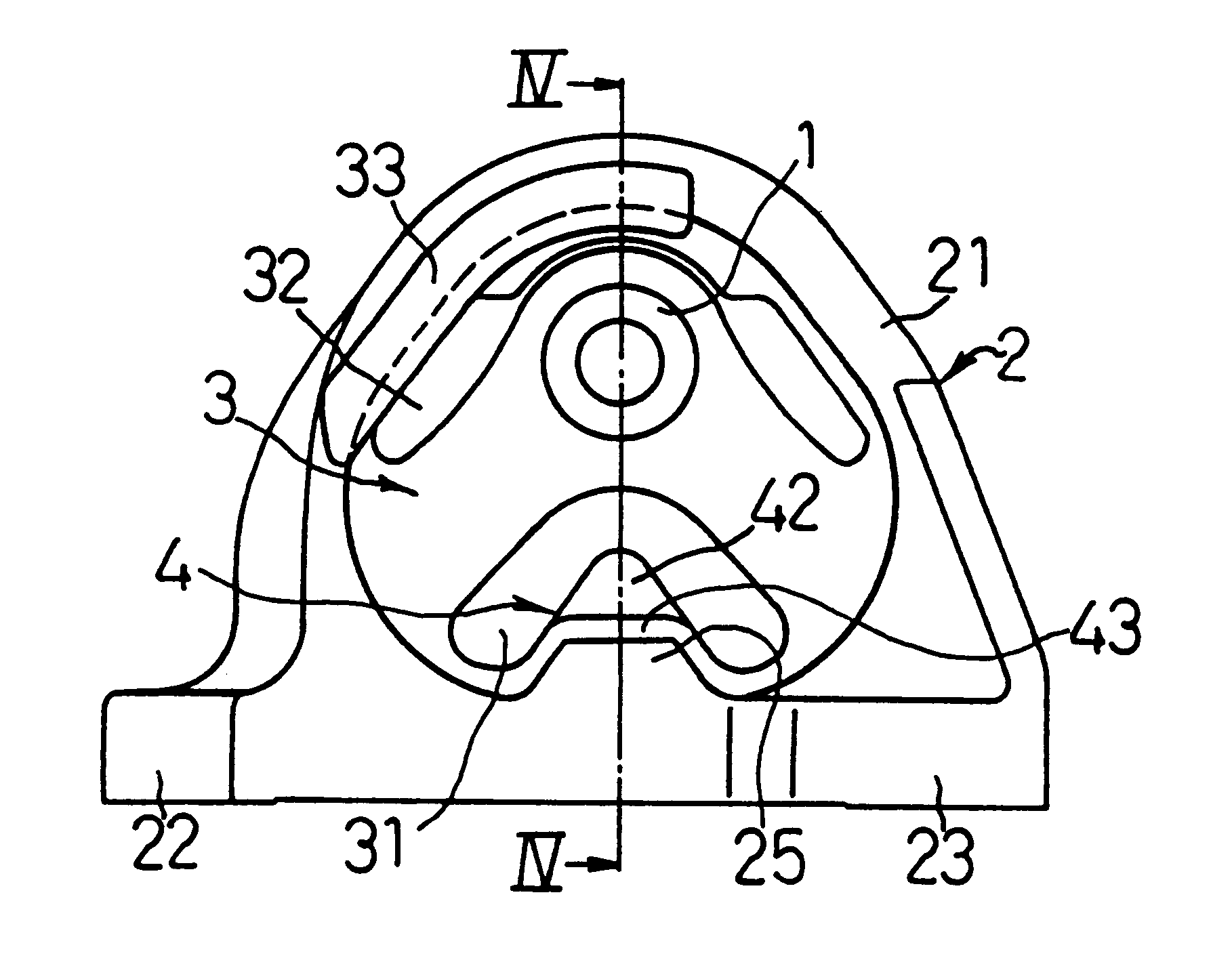
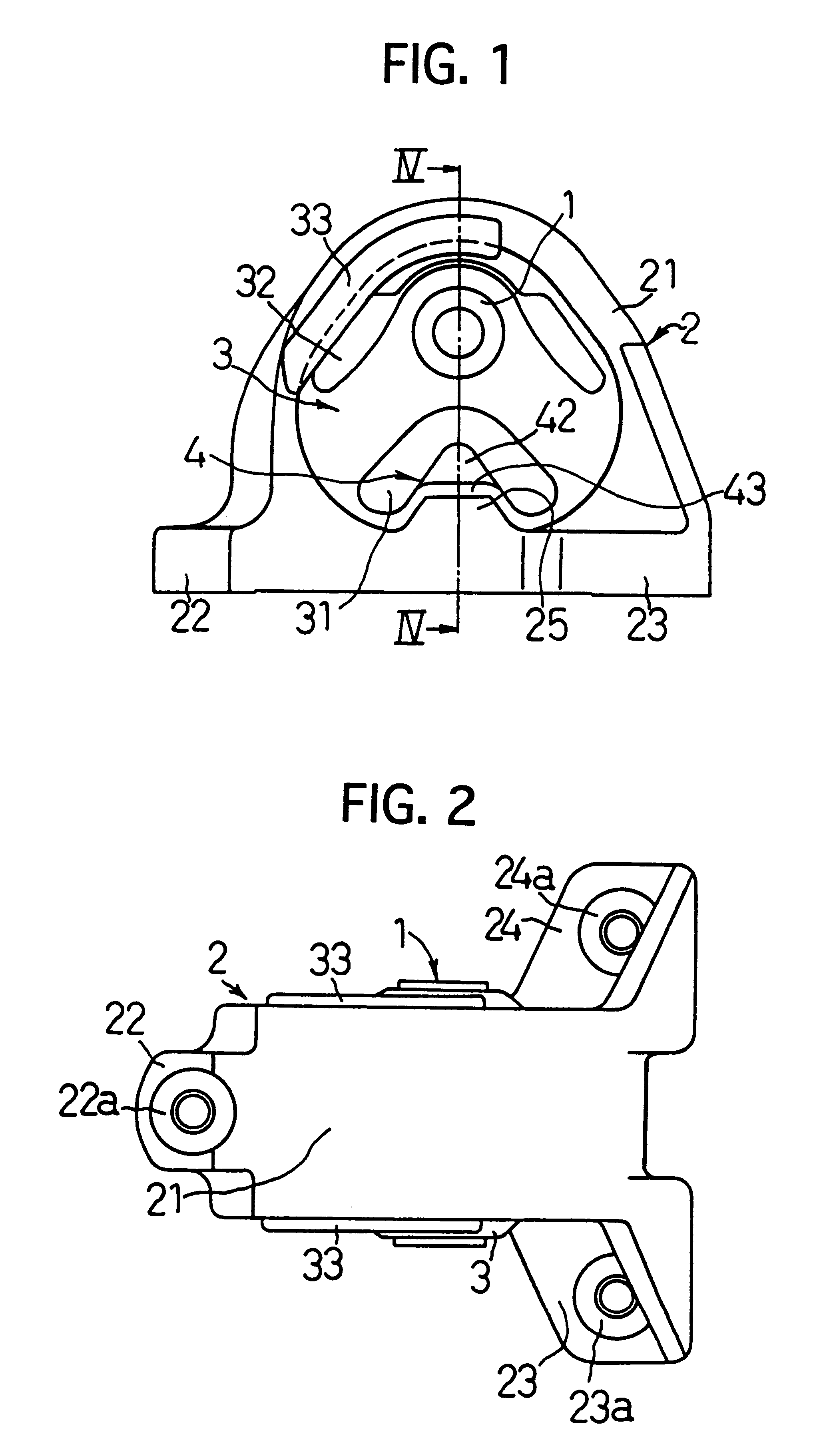
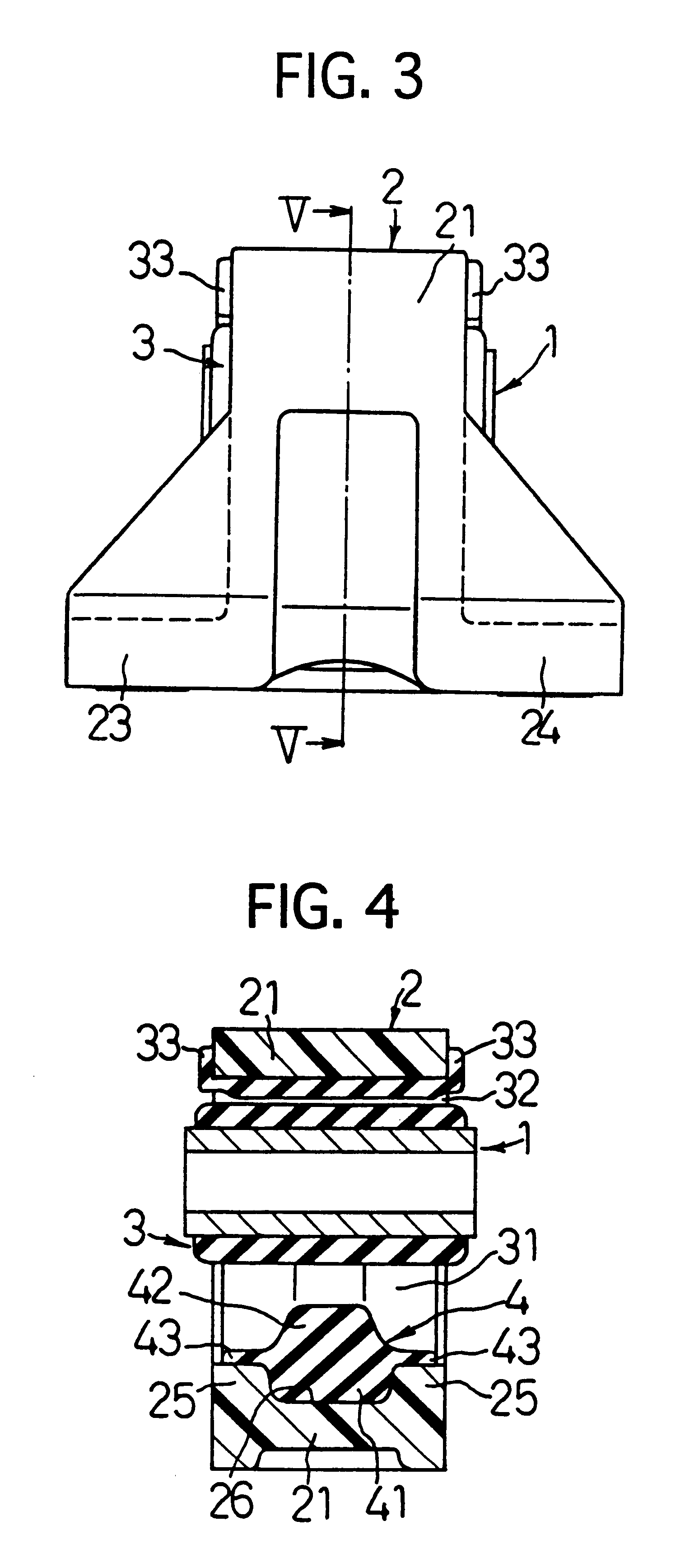
FIG. 1 is a front view of a vibration isolator of the first preferred embodiment of the present invention. FIG. 2 is a plan view of this vibration isolator. FIG. 3 is a side view of this vibration isolator. FIG. 4 is a cross sectional view taken along line IV--IV of FIG. 1. FIG. 5 is a cross sectional view taken along line V--V of FIG. 3.

The vibration isolator of this preferred embodiment mainly comprises, as shown in FIGS. 1 to 5, an inner member 1; a mounting member 2 formed of synthetic resin and having a tubular portion 21 which is disposed outside of and at a distance from the inner member 1 approximately coaxially with the inner member 1; a rubber elastic body 3 disposed between and connecting integrally the inner member 1 and the tubular portion 21, and having axially through cavity portions 31, 32; and an elastic stopper 4 project...


PUM


Abstract

A vibration isolator which can attain both a reduction in the vibration transmitting power and superior durability of an elastic stopper which has a compact stopper structure. This vibration isolator comprises an inner member; a mounting member having a tubular portion which is disposed outside of and at a distance from the inner member approximately coaxially with the inner member; a rubber elastic body disposed between and connecting integrally the inner member and the tubular member and having an axially through cavity portion; and an elastic stopper projecting from an inner circumferential surface of the tubular portion in a manner to face the inner member by way of the cavity portion. This tubular portion has side stoppers which are disposed at both the axial ends of a portion where the elastic stopper is formed, in a manner to face the inner member, and which form therebetween a concave portion depressed in a radially outward direction. The elastic stopper has a projection base portion embedded in the concave portion and projecting in a radially outward direction from fore end surfaces of the side stoppers.

Description

1. Field of the InventionThe present invention relates to a vibration isolator used suitably as, for example, an engine mount which vibroisolatingly supports an engine unit to be mounted on a vehicle.2. Description of the Related ArtConventionally, when an engine unit is mounted on a vehicle, such a vibration isolator as an engine mount is employed to support the engine unit vibroisolatingly, in order to suppress vibrations generated at the engine unit from being transmitted to a car body. An example of the conventional engine mount of this type is shown in FIGS. 11 to 13.This engine mount comprises a cylindrical inner member 5; a mounting member 6 having a tubular portion 61 which is disposed outside of and at a distance from the inner member 5 approximately coaxially with the inner member 5, and two mounting seat portions 62, 63 which are integrally formed at an outer periphery of the tubular portion 61; a rubber elastic body 7 disposed between and connecting integrally the inner ...

Claims


Application Information

Patent Timeline
Patent Type & Authority Patents(United States)
IPC IPC(8): F16F1/387F16F1/38B60K5/12
CPCF16F1/38F16F1/387
Inventor KATO, KAZUHIKOSUZUKI, TATSUYA
Owner SUMITOMO RIKO CO LTD
Features
  • R&D
  • Intellectual Property
  • Life Sciences
  • Materials
  • Tech Scout
  • Unparalleled Data Quality
  • Higher Quality Content
  • 60% Fewer Hallucinations
Learn More