Method for forming a molded edge seal

a technology of molded edges and seals, applied in non-linear optics, instruments, other domestic articles, etc., can solve the problems of affecting performance, affecting performance, and affecting the effect of abrasion

Inactive Publication Date: 2001-04-10
PPG IND OHIO INC
View PDF25 Cites 35 Cited by
  • Summary
  • Abstract
  • Description
  • Claims
  • Application Information

AI Technical Summary

Problems solved by technology

In addition, these devices exhibit long-term retention of a chosen optical state, requiring no power consumption to maintain that optical state.
When the electrode adjacent to the electrochromic film is the cathode, application of an electric field causes darkening of the film.
Absent an adequate seal, moisture loss or gain from / to the ion-conducting material layer may adversely impact performance.
Many laminated objects and devices are prone to moisture gain or loss through their peripheral edge regions.
When an unsealed object is properly inserted in a mold, the mold cavity is contiguous with and covers the portion of the object's peripheral edge region prone to moisture gain or loss.
These polymer interlayers are generally prone to moisture gain or loss.

Method used


Image

  • Method for forming a molded edge seal
  • Method for forming a molded edge seal
  • Method for forming a molded edge seal

Examples


Embodiment Construction

The present invention is more particularly described in the following Example, which is intended to be illustrative only since numerous modifications and variations therein will be apparent to those skilled in the art.

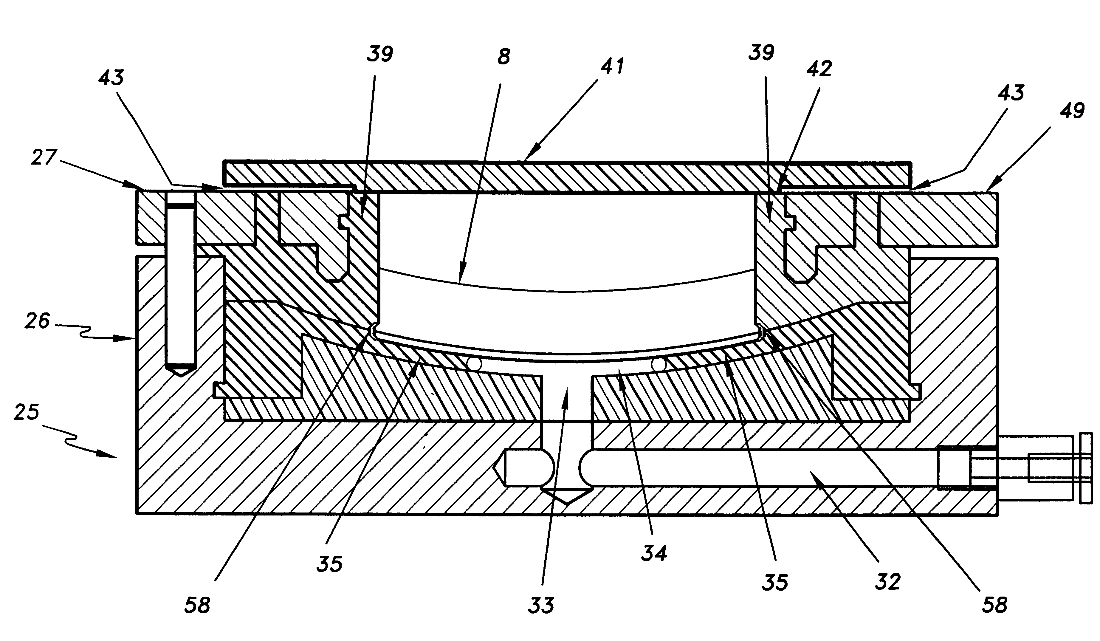
Sealing an Electrochromic Device

A laminated electrochromic device prepared substantially in accordance with Example I of U.S. Pat. No. 5,520,851 was inserted into a split mold in a manner that aligned the cavity of the mold with the ion-conducting polymer interlayer of the device. This split mold was fitted with a top plate having an extended surface that aligned with the pliable portion of the top half of the split mold. Pressure was applied to the pliable portions of the split mold by compressing the mold pneumatically against the top plate and a fixed platen. After application of vacuum to seal the bottom expanse surface of the device against the mold support ledge, Araldite.RTM. 2012 epoxy sealant was injected into the mold cavity via a needle that had been inserte...


PUM

PropertyMeasurementUnit
thicknessaaaaaaaaaa
thicknessaaaaaaaaaa
refractive indexaaaaaaaaaa

Abstract

A method for sealing the circumferential edge region of a laminated electrochromic device is disclosed. The method involves inserting a device to be sealed into a mold having a cavity aligned with the portion of the edge region to be sealed, and injecting a sealant into the cavity. Devices containing molded edge seals are also disclosed.

Description

This invention is directed to a method for sealing an object prone to moisture gain or loss through its peripheral edge region and to the resulting edge-sealed object. In a preferred embodiment, the peripheral edge region of a laminated electrooptic device, for example an electrochromic lens, is sealed by inserting the device into a mold having a cavity aligned with the portion of the device prone to moisture gain or loss, and then injecting sealant into the cavity. After curing, an edge-sealed device is removed from the mold. Novel molds are also disclosed.BACKGROUND OF THE ARTThe optical properties of electrochromic materials change in response to electrically driven changes in oxidation state. Thus, when an applied voltage from an external power supply causes electrons to flow to (reduction) or from (oxidation) an electrochromic material, its transmittance properties change. In order to maintain charge neutrality, a charge balancing flow of ions in the electrochromic device is ne...

Claims


Application Information

Patent Timeline
Patent Type & Authority Patents(United States)
IPC IPC(8): B29C70/00B29C70/76B29D11/00G02F1/01G02F1/161B29C33/38B29C45/14G02F1/15G02F1/153
CPCB29C70/76B29D11/0073G02F1/161B29C33/3857B29C45/14336B29L2009/00
Inventor SMARTO, JOHN E.BOLEY, JEFFERY B.ANTHONY, DONALD
Owner PPG IND OHIO INC
Why Eureka
Try Eureka