
Electro-optical device with integral optical element

Inactive Publication Date: 2001-04-10
BLUE SKY RES
View PDF4 Cites 1 Cited by
  • Summary
  • Abstract
  • Description
  • Claims
  • Application Information

AI Technical Summary

Benefits of technology

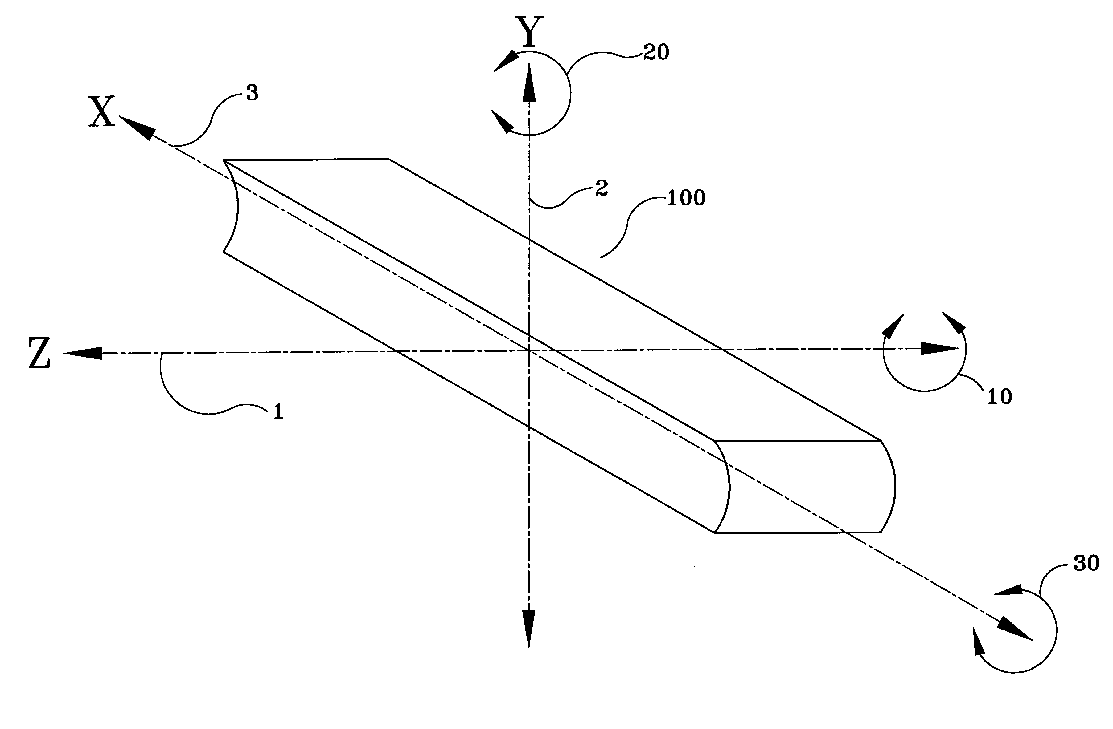
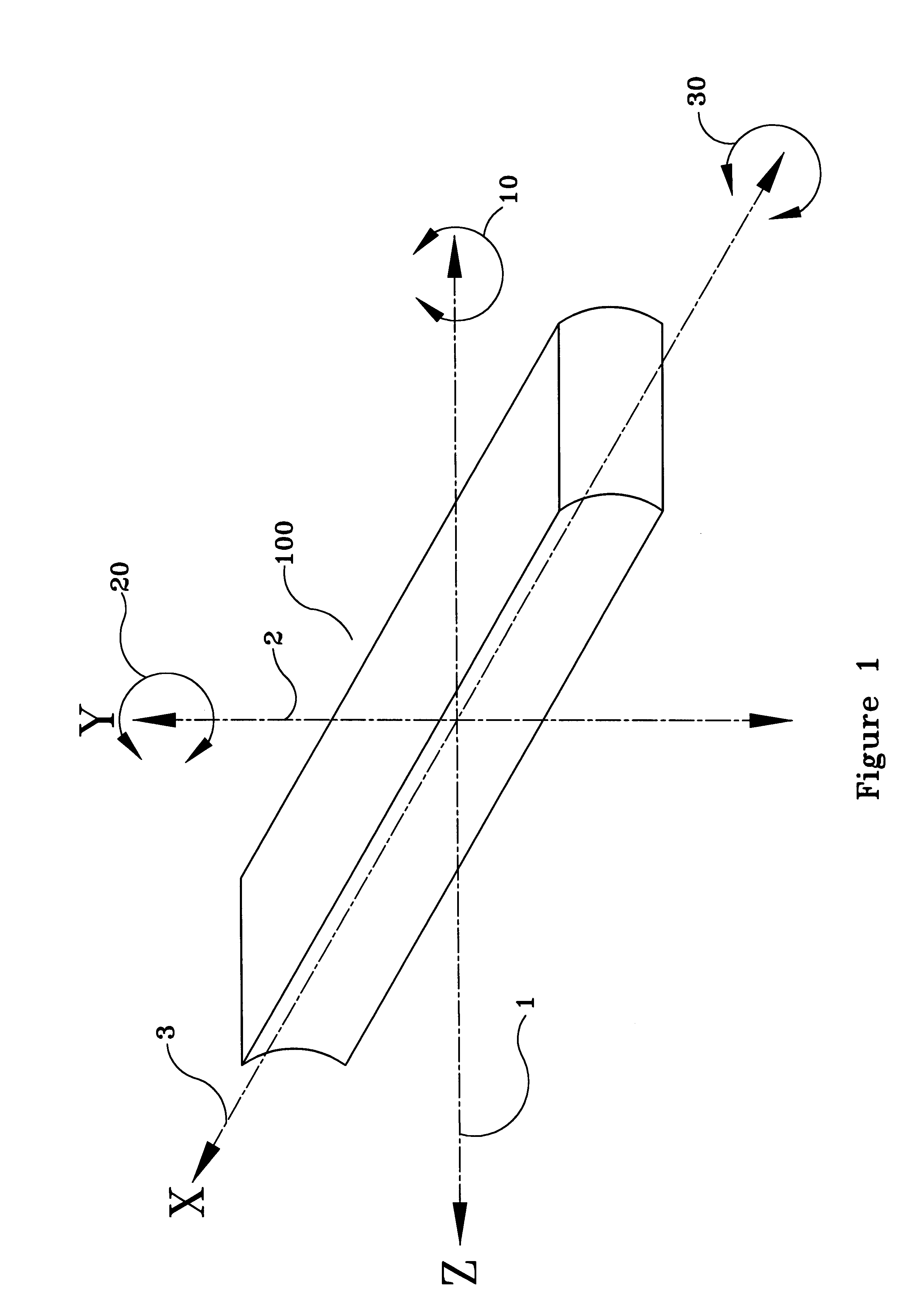
After the attachment of the diode strip to the carrier strip, a length of cylindrical lens is aligned with the diode strip in the following manner: the cylindrical lens is positioned such that its X axis is parallel to the emitter faces of the several diodes in the diode strip. The lens is further aligned along its Y axis such

Problems solved by technology

Laser diodes are efficient sources of laser radiation, however the highly divergent beam emitted from a laser diode presents problems in many applications.
While the above-described laser diode assemblies are fully effective for their intended use, the method of manufacture has heretofore resulted in manufacturing inefficiencies.
It will be apparent to those of ordinary skill in the art that a mechanical translation stage providing the required five degrees of freedom is subject to considerable inaccuracies.
This motion of course tends to misalign the optical elements.
From the foregoing discussion, it is apparent that the current manufacturing process for laser diode assemblies including a cylindrical microlens is a labor-intensive process, requiring considerable effort on the part of skilled technicians to effect the assembly of one lens to one diode.

Method used


Image

  • Electro-optical device with integral optical element
  • Electro-optical device with integral optical element
  • Electro-optical device with integral optical element

Examples


Embodiment Construction

A length of cylindrical microlens, for instance a microlens constructed in accordance with the teachings of at least one of U.S. Pat. Nos. 5,080,706, 5,155,631, and 5,181,224, is fabricated. The length of the lens should be at least equal to the diameter of the crystal wafer from which the laser diodes will be formed.

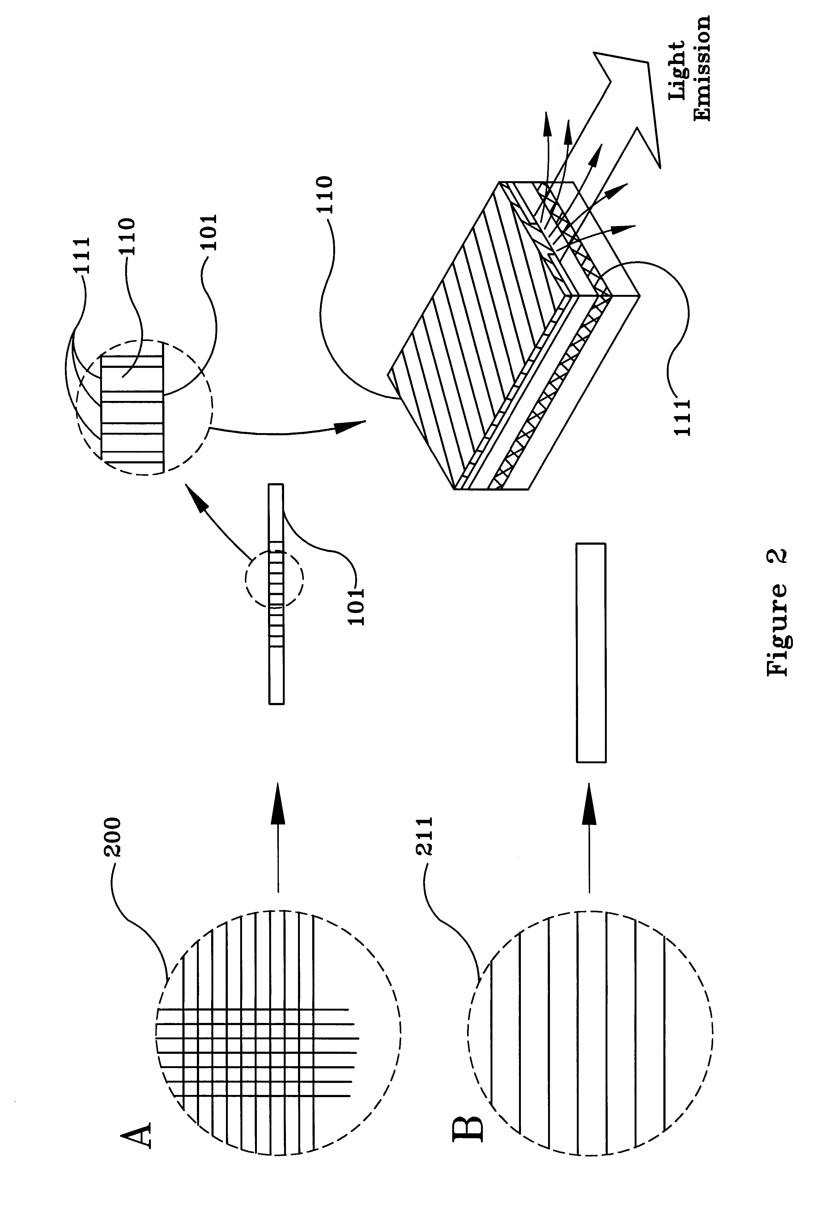
Referring now to FIGS. 2A and 2B, laser diodes are formed in the conventional manner, for instance as discussed in E. A. Gerber et al., Discrete Circuit Components; Alan B. Grebene, et al., Integrated Circuits and Microprocessors; and Richard R. Shurtz II, Semiconductor Lasers and LEDs; all in Electronics Engineers' Handbook, 3rd ed. (Donald G. Fink and Donald Christiansen, eds. 1989), which is hereby incorporated by reference. Diodes 110 are formed on the surface of wafers 200. Laser diodes may be formed on gallium arsenide wafers, and the following discussion assumes the use of gallium arsenide as the substrate for diode production. It should be noted that while galli...


PUM


Abstract

Electro-optical device characterized by having been formed into an individual unit with an integral optical element, and method to form the device. An optical element, for instance a length of cylindrical microlens, is aligned with a diode strip having a plurality of diodes, for instance laser diodes, and attached to the lens. Subsequent to this attachment, the composite structure consisting of the diode strip having attached to it the lens is sectioned into individual diodes, each of which has a integral lens attached thereto.

Description

The present invention relates to a methodology for integrally mounting optical elements to electronic components, and to electronic components so formed with integral optical components. More specifically, the present invention teaches a methodology particularly suited for the mounting of microoptical lenses to laser diodes during the process of manufacturing the diodes, resulting in increased accuracy of lens placement, which methodology requires fewer manufacturing steps to implement than prior mounting methods. The methodology taught herein is particularly well suited for mounting cylindrical microlenses to laser diodes, during the process of manufacturing the diodes, which results in a virtual point source laser diode.U.S. Pat. No. 5,081,639 teaches a laser diode assembly including a cylindrical lens. The laser diode assembly taught therein includes a diffraction-limited cylindrical lens having a numerical aperture greater than 0.5 which is used to collimate a beam from a laser ...

Claims


Application Information

Patent Timeline
IPC IPC(8): G02B3/06G02B3/02G02B7/02H01S5/40H01S5/00H01S3/00H01S5/022
CPCG02B3/06G02B7/02H01S5/4025H01S5/005H01S5/02248H01S5/02325
Inventor SNYDER, JAMES J.
Owner BLUE SKY RES
Learn More