Reinforced variable stiffness tubing

Inactive Publication Date: 2001-04-17
COHEN MARK
View PDF16 Cites 264 Cited by
  • Summary
  • Abstract
  • Description
  • Claims
  • Application Information

AI Technical Summary

Problems solved by technology

The above procedures, however, frequently induce trauma to the walls of the patient's passageways.
Without sufficient torque transmission, the catheter cannot be precisely rotated into the desired body organ.
Further, poor torque transmission causes buckling, wind-up and whiplash, inducing trauma to the passageways and causing pain and discomfort to the patient.
Thus, the medical profession has been faced with a trade-off between a highly flexible catheter apparatus that fails to function adequately when in torsion or a rigid catheter that creates an intolerable amount of trauma.
While this construction produces adequate pushability and kink resistance results for thick walled tubing, it does not address problems inherent in thin-walled tubing.
Unfortunately, due to the construction methods of these catheters, the braid pattern remains constant throughout the entire length of the catheter, with exception of the tip region, therefore compromising performance characteristics through out the different segments of the catheter.
The difficulty in producing a catheter of this nature is that the transition from a "stiff" section to a "soft" section is not achieved continuously.
Rather at each joint, a stress riser may occur that can weaken the tube's structure thereby leading to possible premature kinking when flexed or r

Method used


Image

  • Reinforced variable stiffness tubing
  • Reinforced variable stiffness tubing
  • Reinforced variable stiffness tubing

Examples


Embodiment Construction

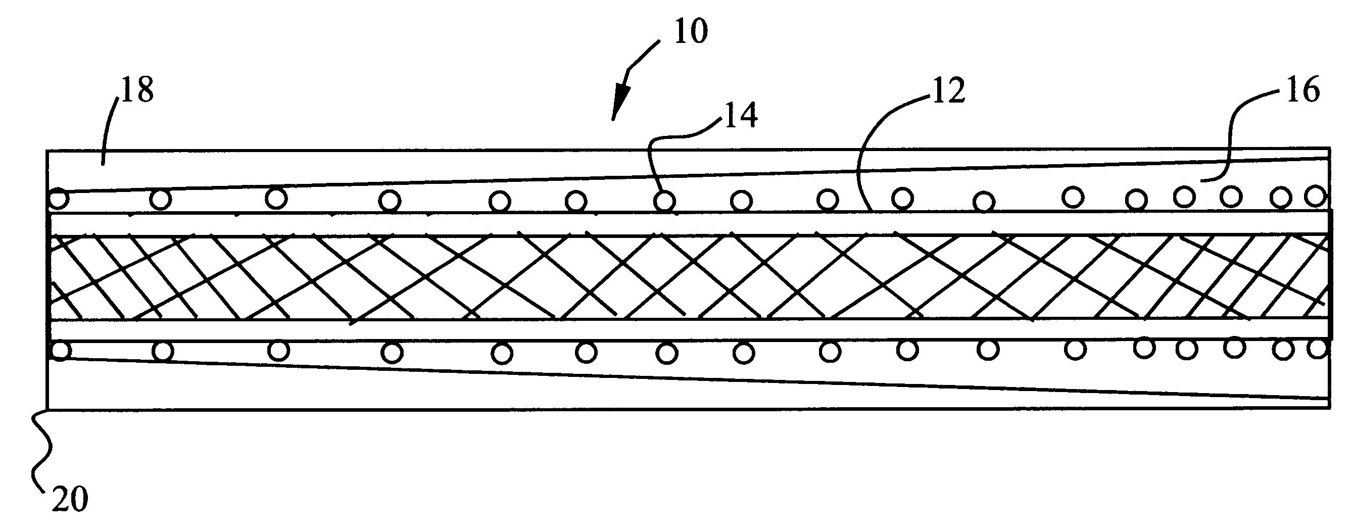
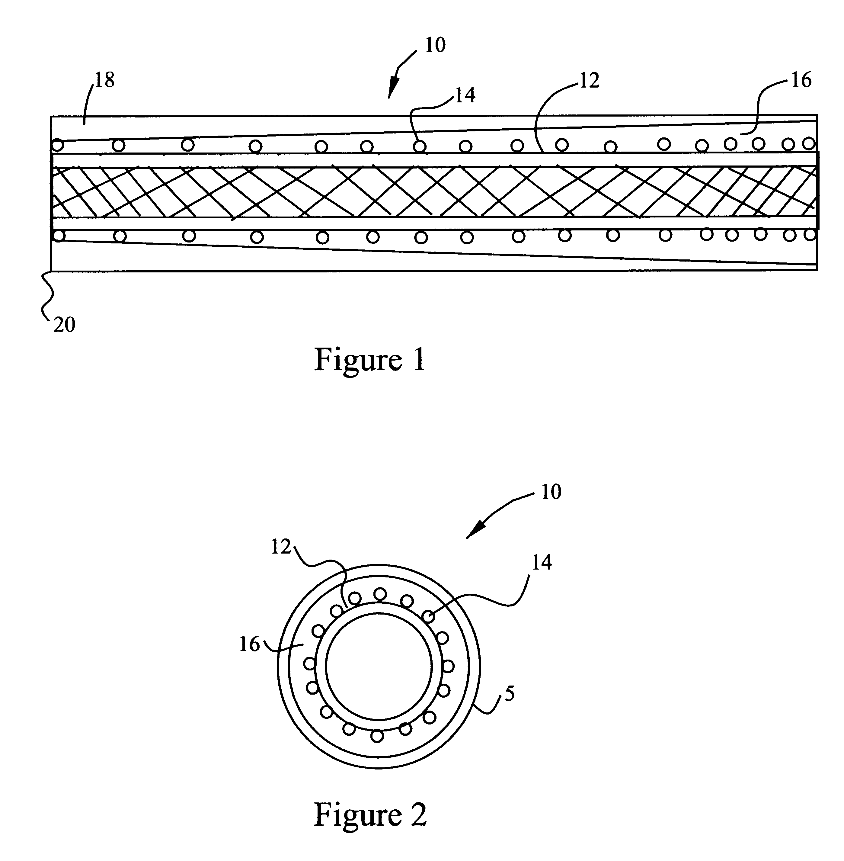
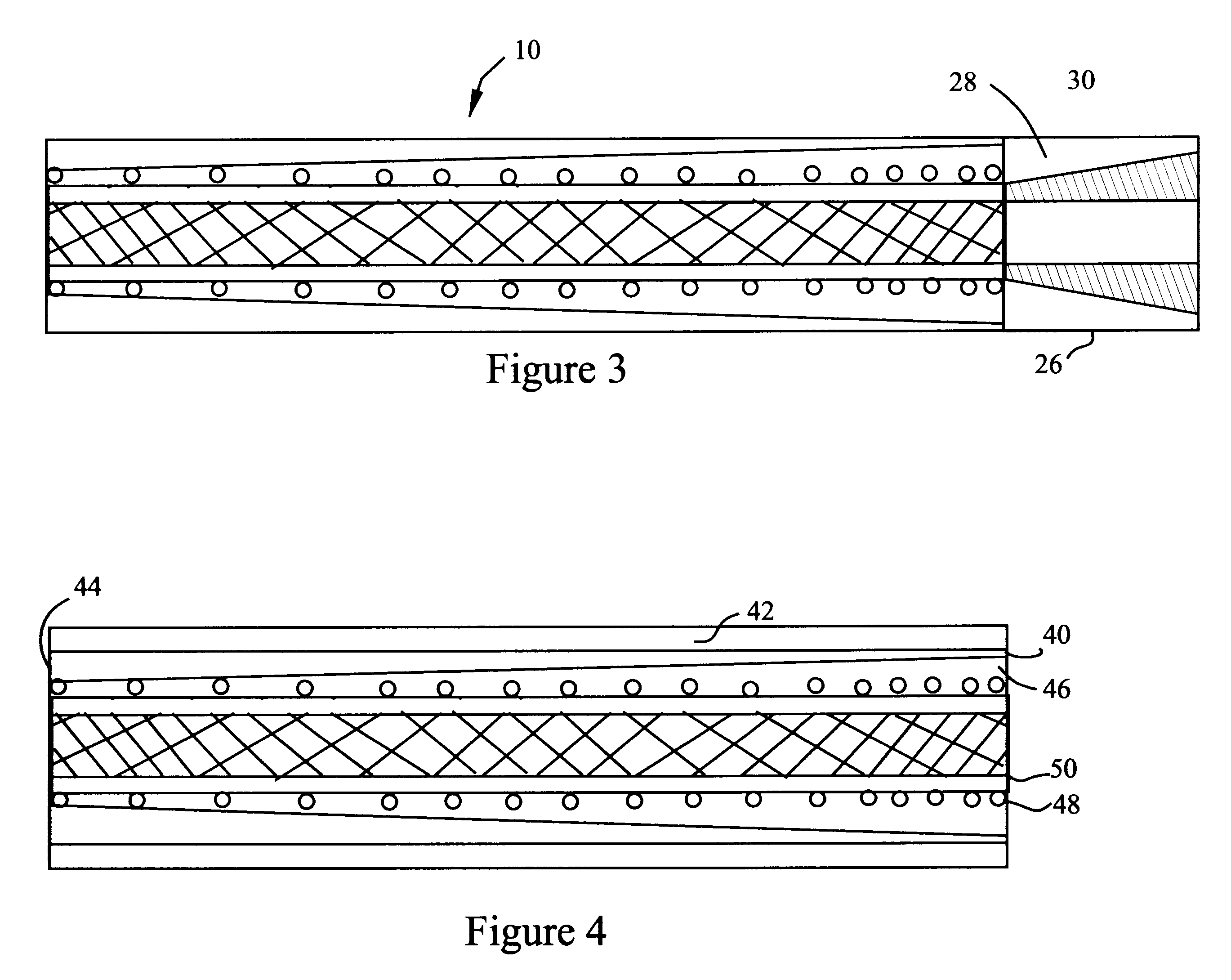
Currently variable stiffness catheters comprise an inner most layer that is comprised of a thin fluoropolymer film. This film is then covered with a braid, which is usually metallic but also can be made of a polymer, such as nylon, high density and linear polyolefines, such as polyethylene, or a composite, such as Kevlar. The actual braid design can be single or side-by-side strands, following a traditional braid pattern. The braid is then coated with at least two component co-tapered.

The cotapered layers of tubing, extend from the proximal to distal ends. In general, the discrete layers differ in durometer as they advance distally, forming a rigid to soft composite construction. Most advantageously the structure softens in durometer from distal to proximal end.

In other applications, a soft tube having a uniform durometer is joined with the braided substrate. A non-braided soft tip is then usually bonded to the distal end. Hubs and strain relief are fitted proximally and the tip is ...


PUM


Abstract

A reinforced catheter having a multi-layered structure suitable for medical uses comprising an inner liner, a braided reinforced layer adjacent to the inner liner, a first resin adjacent to the braided layer, and a harder second resin overlaying the first resin; wherein, the first resin and second resin taper inversely to one another along the length of the catheter, thereby forming a co-tapered soft tip that reduces body trauma.

Description

1. Field of the InventionThe invention discloses reinforced co-tapered, variable stiffness tubing, and more specifically a reinforced tubing using an encapsulated braid.2. Brief Description of the Prior ArtCatheterization procedures are used to diagnose the condition of a patient's body tissue such as arterial passageways or the like. Normally, an incision is made in the patient's body in order to insert the catheter apparatus into the passageways to be diagnosed. The catheter is then inserted through the incision and into the desired passageway. The catheter is fed through the passageway until it is correctly positioned adjacent the desired body organ, such as the heart. The catheter is then precisely rotated and manipulated into the desired body organ, for instance, the right coronary artery. Diagnostic fluid is then injected into the passageway at a predetermined minimum flow rate in order for a separate device, such as an x-ray; to properly record in photograph form the conditio...

Claims


Application Information

Patent Timeline
IPC IPC(8): A61M25/00
CPCA61M25/005A61M25/0053
Inventor COHEN, MARK
Owner COHEN MARK
Why Eureka
Try Eureka