Method and apparatus for producing electron source using dispenser to produce electron emitting portions

a technology of electron emitting parts and dispensers, which is applied in the manufacture of photo-emissive cathodes, thermionic cathodes, electrode systems, etc., can solve the problems of large number of steps and high production costs

Inactive Publication Date: 2001-04-24
CANON KK
View PDF3 Cites 56 Cited by
  • Summary
  • Abstract
  • Description
  • Claims
  • Application Information

AI Technical Summary

Problems solved by technology

This production method in the conventional example has drawbacks that large-scale photolithography etching facilities are necessary and indispensable for forming the elements over a large area, the number of steps is also large, and the production cost is thus high.

Method used


Image

  • Method and apparatus for producing electron source using dispenser to produce electron emitting portions
  • Method and apparatus for producing electron source using dispenser to produce electron emitting portions
  • Method and apparatus for producing electron source using dispenser to produce electron emitting portions

Examples


example 1

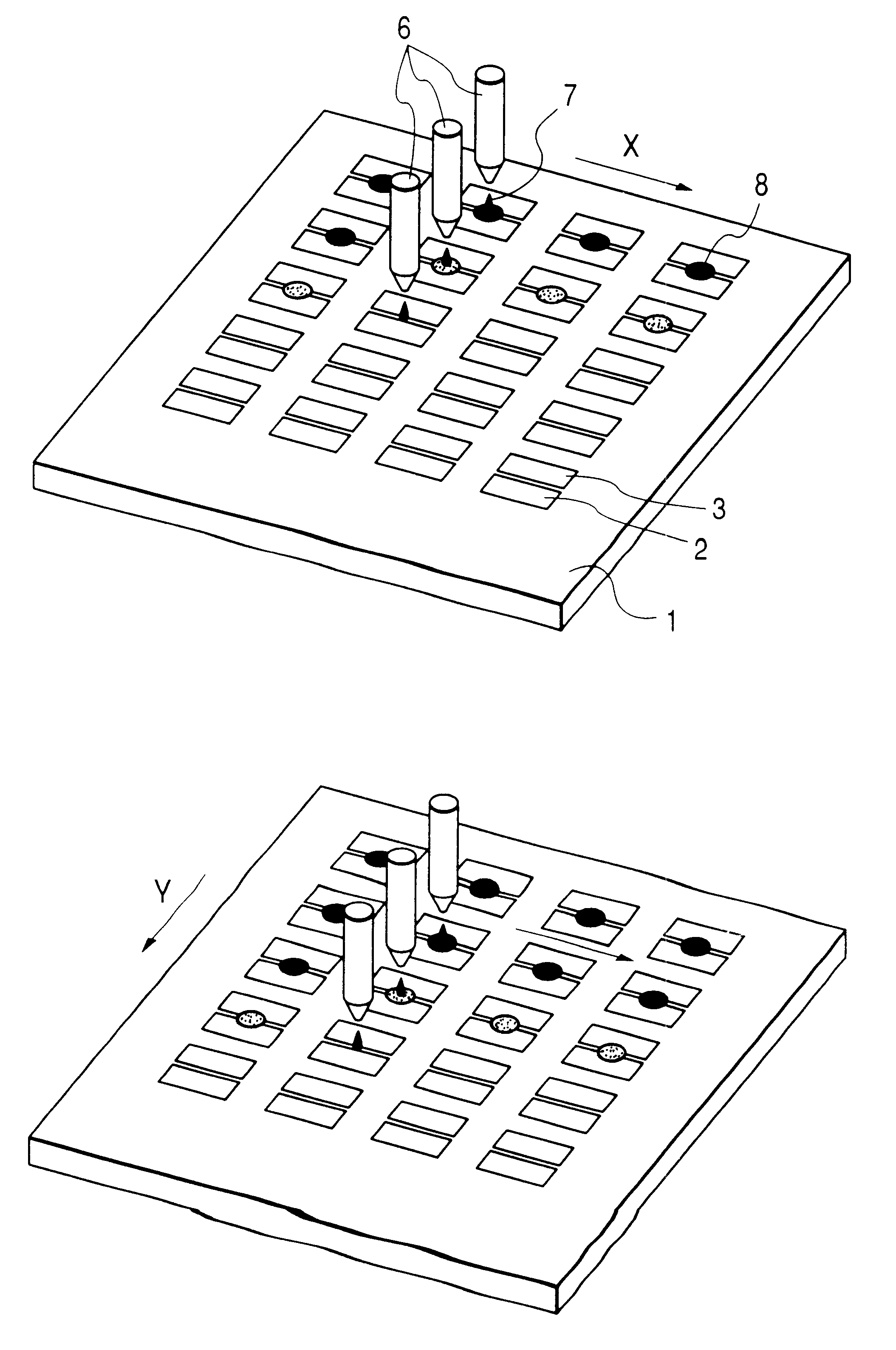
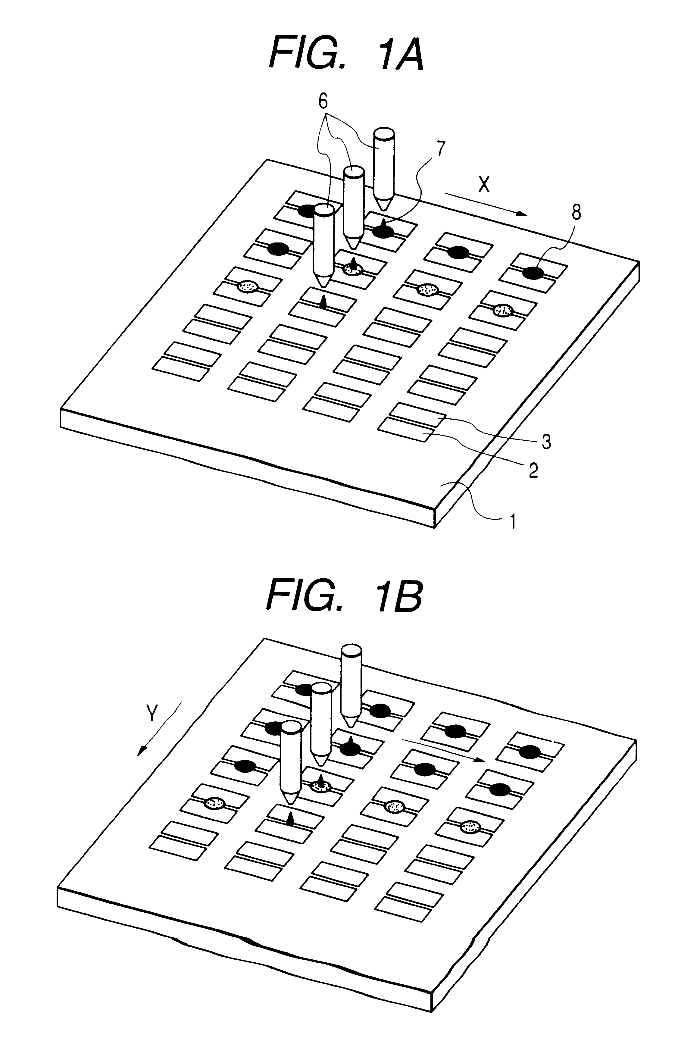
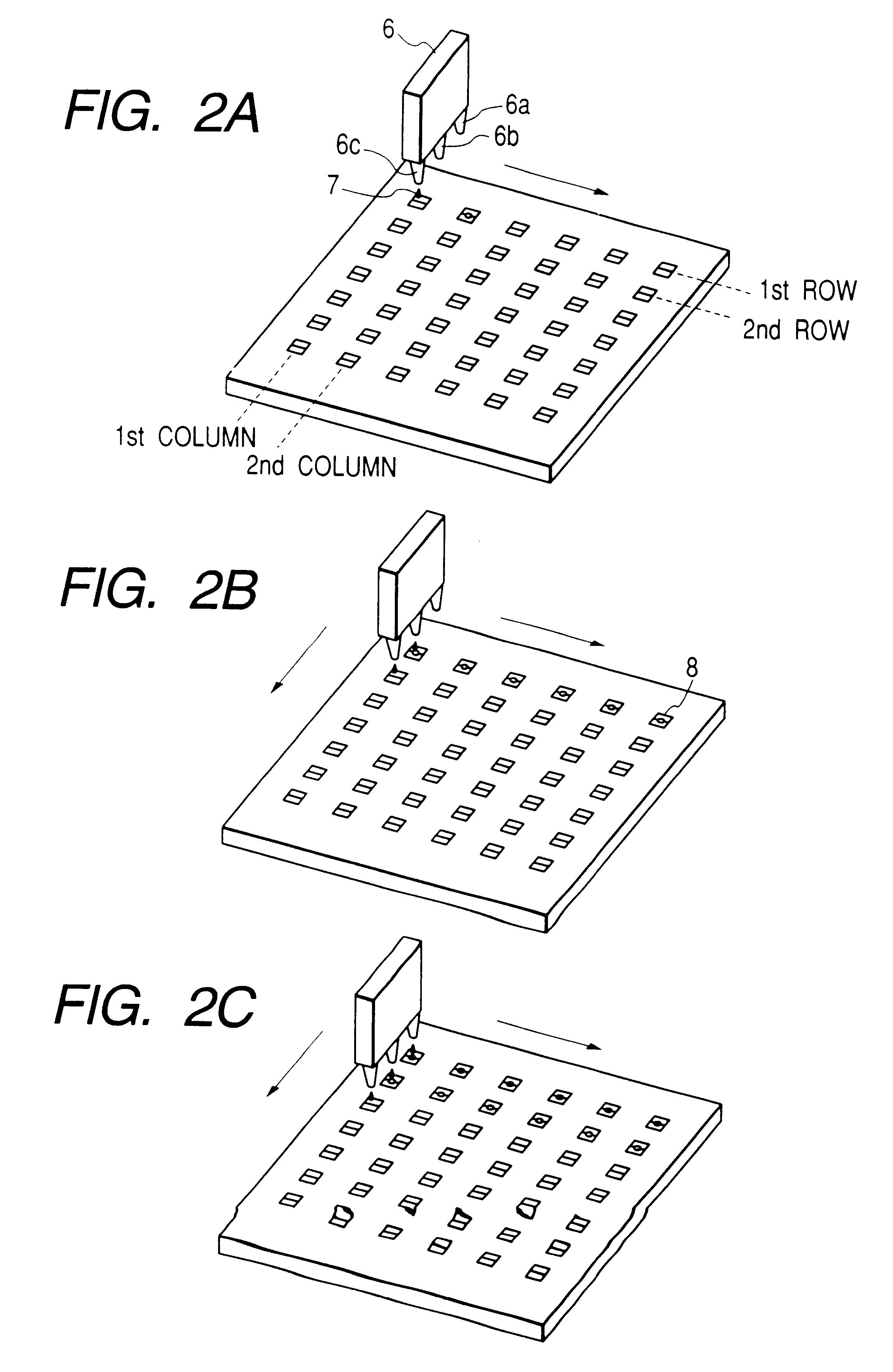
FIGS. 2A, 2B, and 2C are conceptual drawings to show a method for producing the electron source substrate, wherein three droplets are dispensed for each element, using the droplet dispensing device 6 having three nozzles aligned at the same intervals as the element intervals of the electron source substrate. An example of fabrication of this electron source substrate will be described.

First, the insulating substrate was a glass substrate 1. This was washed well with an organic solvent or the like and thereafter it was dried in a drying furnace at 120.degree. C. Using the photolithography processes, a film of Pt (the thickness 500 .ANG.) was deposited on the substrate, the paired element electrodes 2, 3 having the electrode width 200 .mu.m and the electrode gap distance 20 .mu.m were formed in the matrix of 500 rows and 1500 columns, totally 750000, at the intervals of 500 .mu.m in the column direction and at the intervals of 700 .mu.m in the row direction, and the electrodes were co...

example 2

Using the electron source substrate before the forming processing produced by the production method of Example 1, the enclosure was constructed of the face plate 86, the support frame 82, and the rear plate 81 as shown in FIG. 10. Thereafter, an inside is exhaust into vacuum. Similar to the first embodiment, it is subjected to forming, activation and stabilization processing. And, then it is sealed in vacuum. Thereafter, the image forming apparatus was produced by providing it with the driving circuit for TV display based on the television signals of the NTSC method as shown in FIG. 12.

Dispersion in luminance of the image forming apparatus produced in this example was measured and it was 5.7% (standard deviation of luminance / average of luminance) in 75000 pixels. On the other hand, dispersion in luminance of the image forming apparatus, which was produced using the electron source substrate made by dispensing three droplets to each element on the substrate through one nozzle out of ...


PUM


Abstract

In order to suppress variation in delivery amounts in dispensing a material for forming electron emitting portions, a substantially homogeneous material is dispensed from a plurality of output portions to each of plural objective portions. This averages amounts of the material dispensed to the respective objective portions even if there is variation in delivery amounts of material from the respective output portions.

Description

1. Field of the InventionThe present invention relates to a method for producing an electron source having electron emitting portions. The present invention also relates to an electron source produced by the producing method thereof, an image forming apparatus using the electron source, and an apparatus for producing the electron source.2. Related Background ArtThe electron emitting elements conventionally known are roughly classified under two types using thermionic emission elements and cold emission elements. Examples of the cold emission elements are electron emitting elements of a field emission type (hereinafter referred to as "FE type"), a metal / insulator / metal type (hereinafter referred to as "MIM type"), a surface conduction type, and so on. Examples of the FE type known are those disclosed in W. P. Dyke & W. W. Doran, "Field Emission," Advance in Electron Physics, 8, 89 (1956), C. A. Spindt, "Physical Properties of thin-film field emission cathodes with molybdenum cones," ...

Claims


Application Information

Patent Timeline
Patent Type & Authority Patents(United States)
IPC IPC(8): H01J9/02
CPCH01J9/027H01J2329/00
Inventor SHIGEOKA, KAZUYAHASEGAWA, MITSUTOSHIMISHIMA, SEIJISANDO, KAZUHIRO
Owner CANON KK
Why Eureka
Try Eureka