Fluid management system for electrokinetic remediation

a technology of electrokinetic remediation and fluid management system, applied in the field of electrokinetic phenomena, can solve the problems of net loss of water from the vicinity of some electrodes, net gain of fluid in the vicinity, and high fluid loss around some electrodes

Inactive Publication Date: 2001-04-24
LYNNTECH COATINGS
View PDF22 Cites 15 Cited by
  • Summary
  • Abstract
  • Description
  • Claims
  • Application Information

AI Technical Summary

Problems solved by technology

This may cause a net loss of water from the vicinity of some electrodes and a net gain of fluid in the vicinity of other electrodes.
In a given electrode array, the regions around some electrodes may experience high fluid losses while other electrodes in the array may experience large fluid gains.
Contaminants present in soil tend to accumulate in the vicinity of the electrodes as well as in the electrode wells.
This results in an overall loss of fluid from the system.
However, when a site is 30 to 50 feet square and 20-50 electrodes are required for electroremediation, having four fluid lines connected to each well is impractical to install and manage.
Depending on the application, it is possible for the anode to generate potentially toxic or noxious gases.
Other electrodes may experience high current and are subject to great changes in pH.

Method used


Image

  • Fluid management system for electrokinetic remediation
  • Fluid management system for electrokinetic remediation
  • Fluid management system for electrokinetic remediation

Examples


example 2

(Hypothetical)

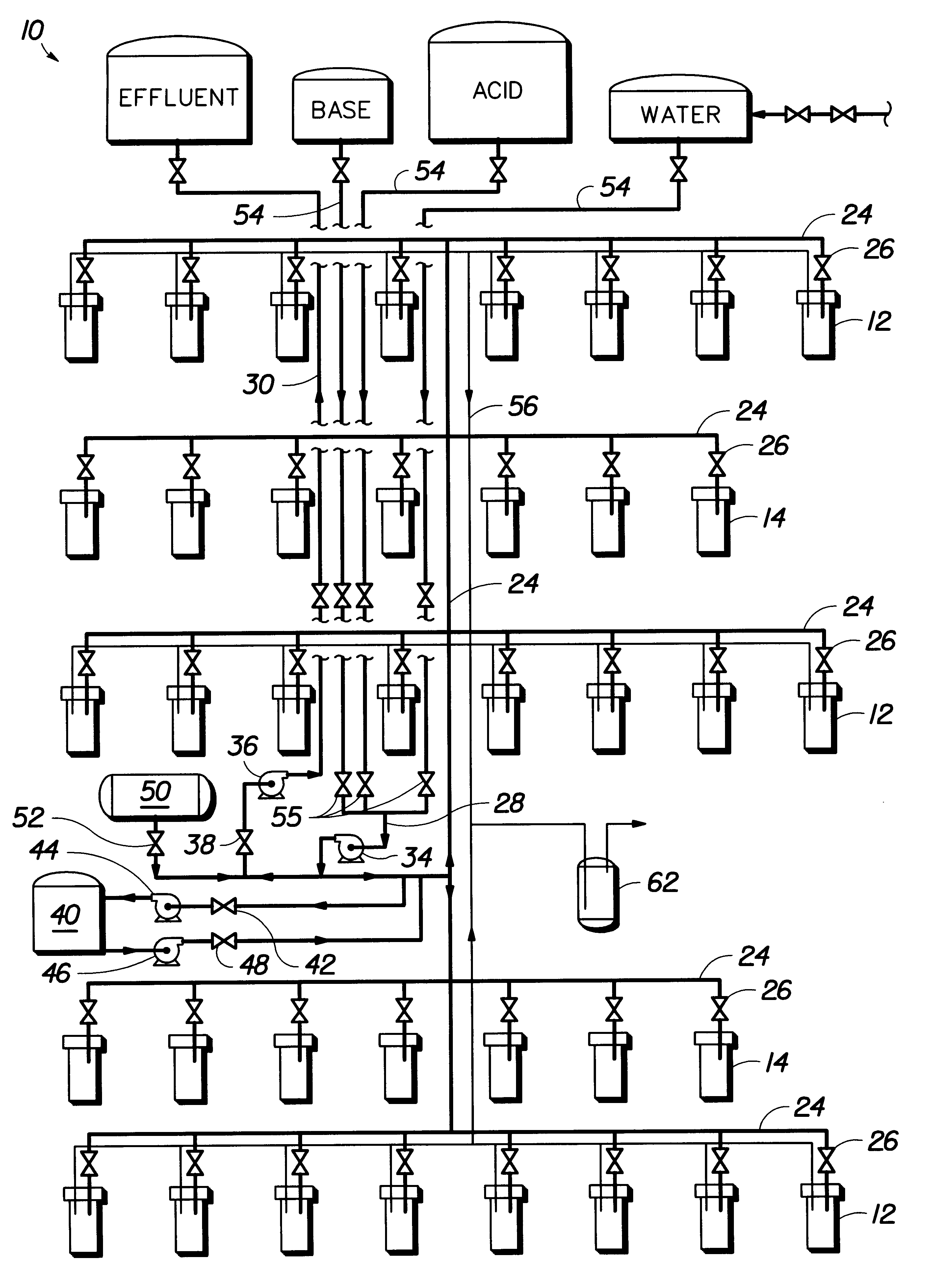
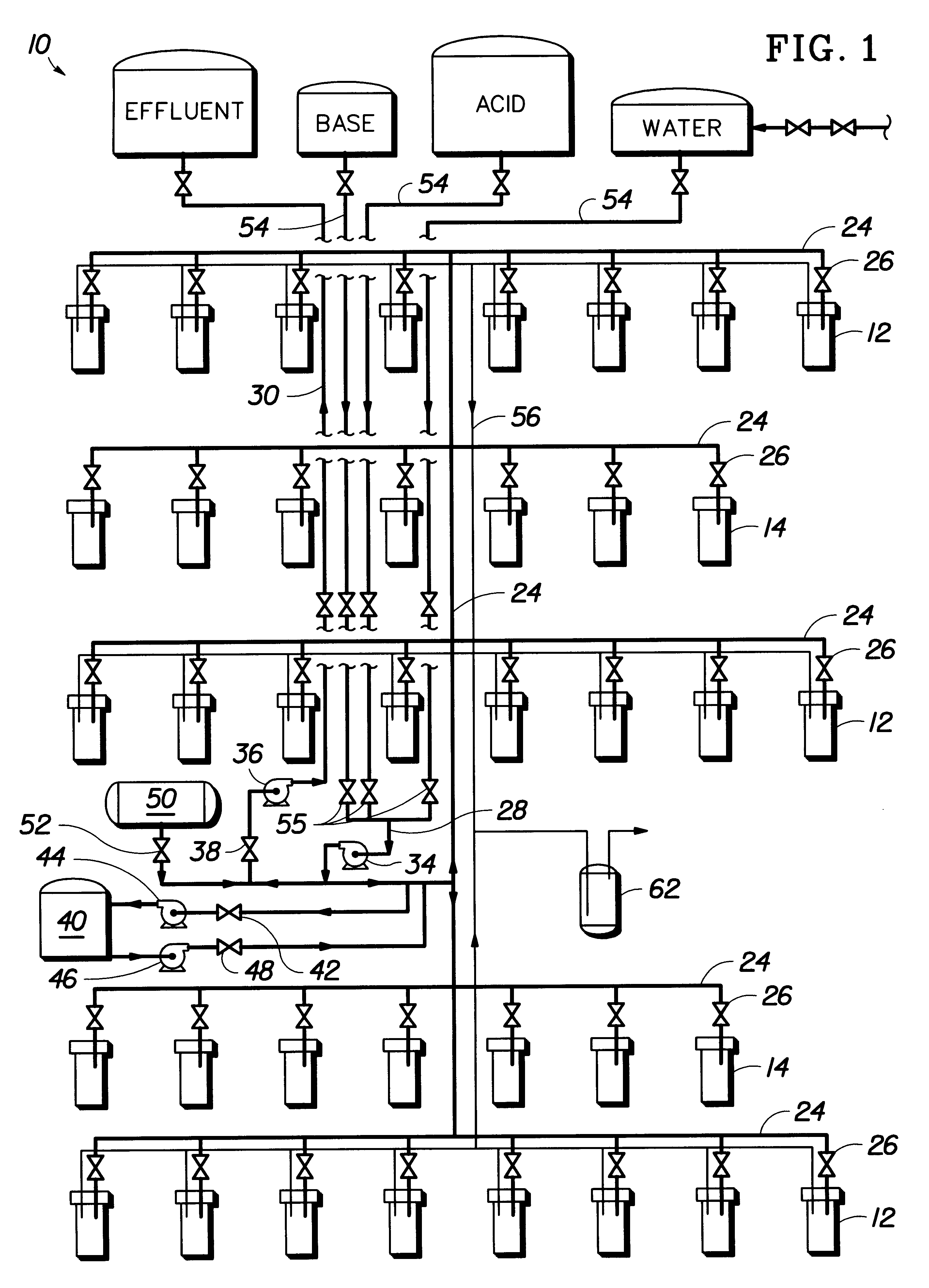
The system disclosed above may be used at a site having the following soil conditions: high water table, clay soil, and metallic contaminants such as chromium and cadmium. The water table is high, (i.e., it is at least higher than the lowest point of the electrode wells below the surface). The soil matrix immediately surrounding the wells is saturated with water, so the tendency is for fluids not to flow out of the well in significant amounts when electroremediation is turned off. The predominately clay-type soil in the vicinity of the electrode array causes electroosmotic flow to occur through the soil between the electrodes. Some electrode wells will accumulated fluids, others will lose fluids, depending upon the direction of electroosmotic flow.

After the electroremediation process is started, the monitoring, fluid chemistry adjustment, and fluid withdrawal steps would be carried out in the same manner as in Example 1. A fluid level adjustment step would be carried o...

example 3

(Hypothetical)

The system disclosed above may be used at a site having the following soil conditions: low water table, sandy soil, and metallic contaminants such as chromium and cadmium ions. The water table is low (i.e., it is at least lower than the lowest point of the electrode wells below the surface). The soil matrix immediately surrounding the wells is, therefore, not saturated with water, so the tendency is for fluids is to drain out of the well in significant amounts on a continuous basis. The soil conditions are predominantly of a sandy type so that electrically-driven electroosmotic flow does not occur through the soil between the electrodes during electroremediation. After the electroremediation process is started, the following fluid management steps are used in conjunction with the apparatus similar to that shown in FIG. 1. The monitoring, fluid chemistry adjustment, and fluid withdrawal steps are carried out according to Example 1. Fluid level adjustment step is require...


PUM

PropertyMeasurementUnit
thicknessaaaaaaaaaa
pHaaaaaaaaaa
pHaaaaaaaaaa

Abstract

A system for managing fluids used during electroremediation of contaminants in a porous medium, such as soil is disclosed. The system monitors the fluid gain and loss from the electrode wells and maintains optimal fluid levels in the wells on an individual basis. The system may use a sensor element for measuring the metal ion content of the electrode well fluid. A method for using the fluid management system is also disclosed.

Description

The present invention relates to a system and method for managing fluids used during electroremediation of contaminants in a porous medium, such as soil.BACKGROUND OF THE RELATED ARTElectrokinetic phenomena include electromigration, electroosmosis, and electrophoresis. Electroosmosis is defined as the mass flux of a fluid containing ions through a stationary porous medium caused by the application of an electrical potential. The fluid moves through the voids in the porous medium (e.g. soil) called pores. Each pore has a thin layer of charged fluid next to the pore wall having a typical thickness of between about 1 and about 10 nanometers. The thin layer of charged fluid next to the pore wall is present to neutralize the charge on the surface of the soil particle that forms the pore wall. Fluid movement occurs in soil pores because of the charge interaction between the bulk of the liquid in the pore and the thin layer of charged fluid next to the pore wall. Under the influence of a D...

Claims


Application Information

Patent Timeline
Patent Type & Authority Patents(United States)
IPC IPC(8): B01D61/42B01D61/56B09C1/00B09C1/08C02F1/469
CPCB01D61/56B09C1/085C02F1/469C02F2201/4612
Inventor HITCHENS, G. DUNCANHODKO, DALIBOR
Owner LYNNTECH COATINGS
Why Eureka
Try Eureka