Non-contacting temperature sensing device

a temperature sensing device and non-contact technology, applied in the direction of optical radiation measurement, fire alarms, instruments, etc., can solve the problems of not all types of infrared sensors being suitable for such applications, not stating or suggesting which type of infrared detectors to us

Inactive Publication Date: 2001-04-24
MONTEREY RES LLC +1
View PDF28 Cites 71 Cited by
  • Summary
  • Abstract
  • Description
  • Claims
  • Application Information

AI Technical Summary

Problems solved by technology

In the case of surfaces with temperatures near or below room temperature, for example, the road surface temperature in winter, the infrared radiation therefrom impinging on the infrared sensor is very weak.
Therefore, not all types of infrared sensors are suitable for such applications.
However, this patent does not state or suggest which type of infrared detectors are suitable candidates.
Due to various factors, the window tends to become contaminated with dust, water, spray, etc., while the vehicle is in motion.
Thermopile detectors are known to have long thermal time constant, thus can not respond to fast changes in temperature.
Pyroelectric type detectors are intrinsically sensitive to mechanical vibration and shocks, thus are not suitable in a vibrating environment such as on-board a moving vehicle.
Pyroelectric type detectors also need a chopper to modulate the incident radiation, complicating the system.
Therefore, the temperature interpretation based on constant emissivity assumption is not always valid.

Method used


Image

  • Non-contacting temperature sensing device
  • Non-contacting temperature sensing device
  • Non-contacting temperature sensing device

Examples


Embodiment Construction

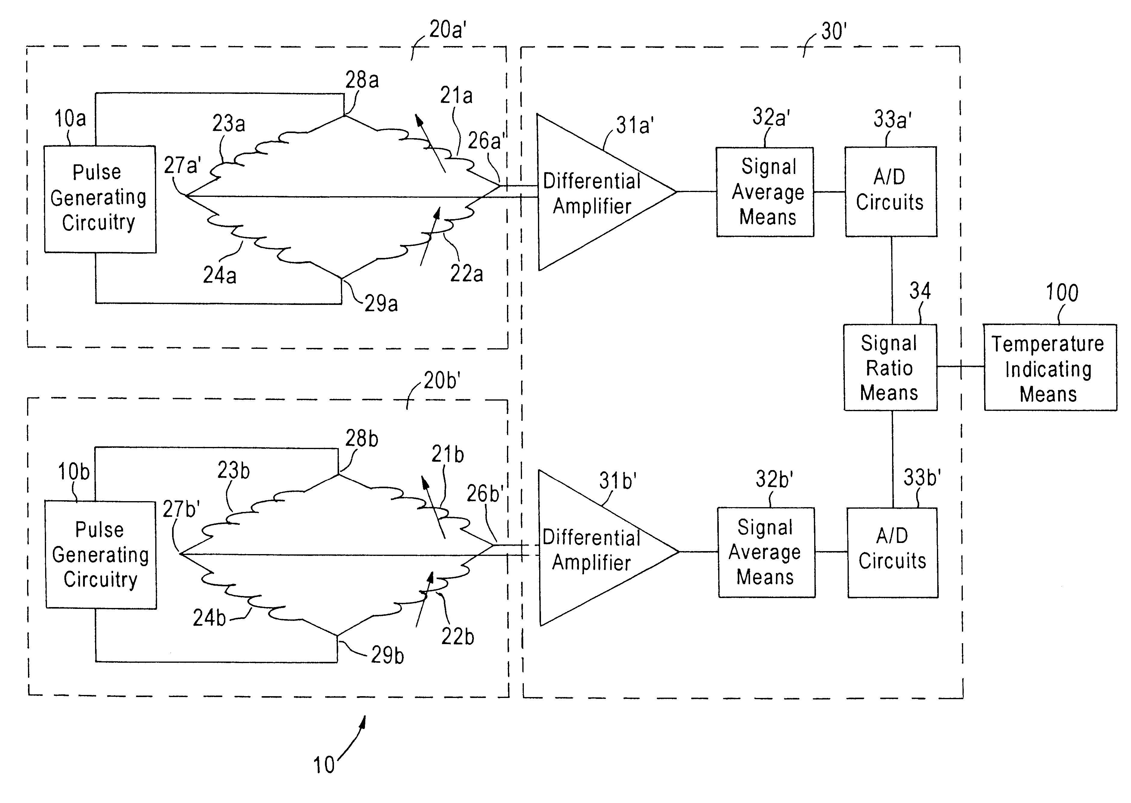
The invention concerns a non-contacting temperature sensing device 10, particularly used for automotive applications, although it will be apparent to those skilled in the art that other applications can be contemplated for the non-contacting temperature sensing device 10 of the invention.

The device 10 includes a first infrared sensing means 20a for detecting radiation within a first wavelength band and for producing a first signal corresponding to the detected infrared radiation of the first wavelength band. The device 10 also includes a second infrared sensing means 20b for detecting radiation within a second wavelength band which is different from the first band and for producing a second signal corresponding to the detected infrared radiation of the second wavelength band. The devices further includes signal processing means 30 for obtaining the ratio of the first and second signals in order to provide a third signal which is emissivity independent and proportional to temperature...


PUM


Abstract

The device according to the invention provides a non-contacting temperature sensing device incorporating micro-bolometric detectors as the suitable infrared sensors for automotive applications. A first and second infrared sensors each include an active infrared sensing element and a temperature drift compensating element. A current bias is applied to the active infrared sensing element as well as to the temperature drift compensating element, which is identical in structure with the active infrared sensing element, and the voltage outputs of these two elements pass through a differential amplifier. The fluctuation in the substrate temperature or the ambient temperature affects the active sensing element and the compensating element in the same way, thus it is cancelled out. Instead of using one spectral band of the infrared radiation, as in the prior art, two spectral bands are used resulting in a first and second signal generated by the first and second infrared sensors. A ratio of the first and second signals is obtained. The ratio of the signals is emissivity independent, so that the device of the present invention provides a more accurate measurement of temperature. The need to compensate for window contamination is also eliminated by this two band approach. The filtering elements for the two bands can be multi-layer thin film filters either coated on flat windows or on diffractive micro-lenses. The use of diffractive micro-lenses further reduces the size of the device, and eliminates the need for a separate optical lens.

Description

The present invention relates to a device for the non-contacting temperature measurement of a surface, for example, the surface of a roadway, from a moving vehicle, using an emissivity independent infrared radiation detection method and infrared detectors, although the invention is not limited in scope to automotive applications.DESCRIPTION OF THE PRIOR ARTOne important aspect of automobile related inventions is to improve the safety features. It has been found desirable to be able to remotely measure the road surface temperature from a moving vehicle in an accurate way, either for predicting the likelihood of icing formation or for warning of overheated surface. Earlier road condition monitoring systems used ordinary thermistors to measure the ambient temperature close to road surface as an approximation for the actual surface temperature. Essentially, these systems include a temperature sensing means for measuring the temperature and means for providing a warning if the measured t...

Claims


Application Information

Patent Timeline
Patent Type & Authority Patents(United States)
IPC IPC(8): G01J5/02G01J5/20G01J5/60
CPCG01J5/0022G01J5/08G01J5/0806G01J5/20G01J5/24G01J5/602G01J2005/0048G01J5/80
Inventor HARLING, GORDZHANG, ROSEPOPE, TIMPICARD, FRANCISAZELMAD, ABDELLAH
Owner MONTEREY RES LLC
Why Eureka
Try Eureka