In the
contact method, an edge of the end portion of the surface of the developing roller for conveying toner comes in direct contact with the photosensitive member, which can undesirably damage the photosensitive member.
If the developing roller is made of a
solid material, such as
metal, even a non-contact development method encounters damage of the photosensitive member attributable to sliding and friction depending upon the accuracy in the deflection of the developing roller and that of the photosensitive member, as well as the contact development method.
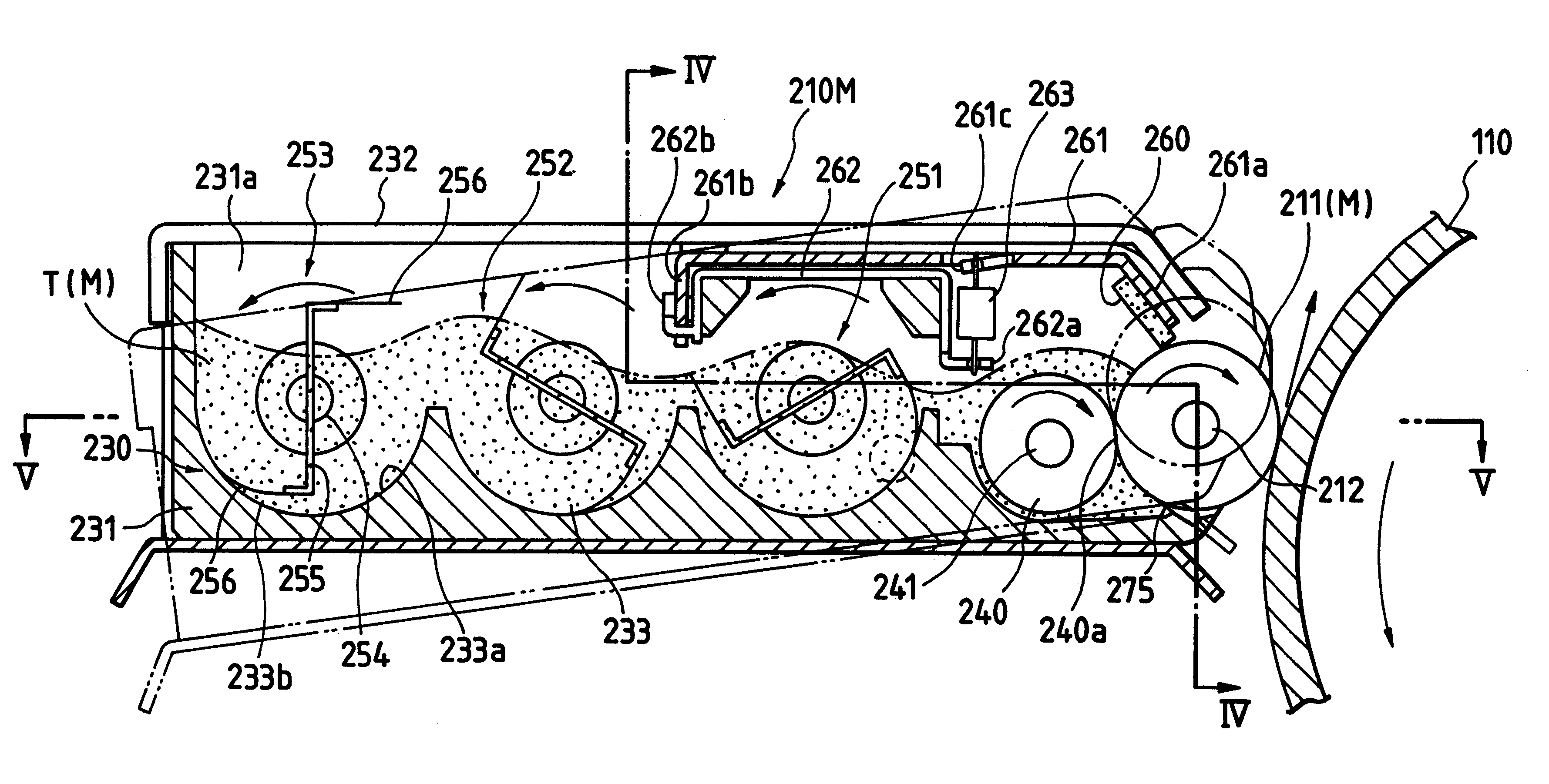
If such compression is continued, the pressure in the case at the positions near the developing roller is excessively raised by the restraining blade to appropriately restrain toner on the developing roller.
The excessive conveyance of toner from the restraining blade changes the density of a formed image and causes toner to be leaked.
If color toner having unsatisfactory fluidity as compared with that of black toner is used, the above-mentioned compression becomes more critical because color toner having poor fluidity is continuously conveyed in the developing unit, and excess toner cannot be returned from the supply roller.
If the conventional developing unit performs a development process with dense toner having poor fluidity, the conveying fin generates a great rotational load which undesirably changes the necessary torque thereby causing rotation of the motor which drives the conveying fin.
As a result, jitters appear in the formed image.
Moreover, the conventional developing unit suffers the problem that filming of the electrified members (such as the developing roller and the restraining blade), easily occurs because of mechanical contact and friction when the development process is performed using dense toner containing a large quantity of
pigment.
When the
electrification characteristic of the toner is instable, the density of the formed image is lowered and the toner supply characteristic deteriorates.
Therefore, in the known contact development method, the photosensitive member is damaged because the sealing portion directly slides on the photosensitive member.
When the developing roller is made of a
solid material, such as
metal, even a non-contact development method encounters damage of the photosensitive member attributable to sliding and abrasion depending upon the accuracy in the deflection of the developing roller and that of the photosensitive member, as well as the contact development method.
One problem encountered by the conventional developing unit is that the portion of the elastic supply roller pressed against the developing roller is dented, causing end portions of the supply roller to project sideways.
The projecting portions then undesirably engage the sealing member, thereby requiring an excessively large drive torque in order to rotate the supply roller.
Another problem with the foregoing conventional developing unit arises from the hardening of the supply roller.
As a result, the
hardness of the expanded material is increased excessively after being used for a long time.
The problem associated with the increase in
hardness of the supply roller is that great torque is required to rotate the supply roller.
However, in recent years, the average particle size of toner has been reduced to 9 .mu.m, and toner having such
small particle size easily clogs in the cells formed in the surface of the conventional supply roller.
The elastic characteristic of the supply roller thus deteriorates in a relatively short time.
Another problem in the foregoing conventional developing unit is that, if the rotational speed of the developing roller is increased to quickly form images, or if the fluidity of toner is increased to maintain the required toner supply characteristic, then toner is introduced into the end surface (the side surface) of the developing roller when the developing roller is rotated.
As a result, toner leaks from the end surface of the developing roller into the image forming portion thus causing the inside portion of the image forming apparatus to be contaminated.
Another problem associated with increased rotational speed of the developing roller and increased fluidity of toner is the leakage of toner from the lower surface of the developing roller during rotation of the developing roller.
This also contaminates the inside portion of the image forming apparatus.
When the image forming apparatus is contaminated in either above manner, it produces a defective image.
Another problem in the above-mentioned conventional developing unit is that an edge of the end portion of the surface of the developing roller comes in direct contact with the photosensitive member thereby causing damage to the photosensitive member.
The photosensitive member is also damaged by direct
sliding contact with the sealing portion of the developing roller when a contact development method is used.
In either case, if the developing roller is made of a
solid material, such as
metal, even a non-contact development method causes damage to the photosensitive member attributable to sliding and friction depending upon the accuracy in the deflection of the developing roller and that of the photosensitive member.
Another problem in the above-mentioned conventional developing unit arises in the conveyance of toner.
As a result, toner on the developing roller cannot be restrained by the restraining blade, which leads to an excess conveyance of toner that causes undesirable changes in the density of the image and also causes undesirable toner leaks.
The above problems are exacerbated when color toner is used.
If color toner having poor fluidity is continuously conveyed in the above-mentioned developing unit, excess toner cannot be returned from the supply roller, which makes the state of compression more critical.
Additional problems with the conventional developing unit arise when color toner is used.
However, if the
pigment component in the toner is increased, the fluidity of the toner generally deteriorates, thus causing a great rotational load on the conveying fin.
The increased load on the conveying fin undesirably changes the necessary torque to drive the conveying fin which in turn causes undesirable changes in the rotation of the motor which drives the conveying fin.
As a result, jitters appear in the formed image.
As a result the density of the formed image is lowered and the toner supply characteristic deteriorates.
Further problems arise in the above-mentioned conventional developing unit when trying to reduce its size.
However, such an arrangement suffers the problem that the conveying fin scrapes insufficient toner up to the surface of the toner supply roller thereby causing an undesirably
low density in the formed image.

