Groundwater flow measuring system

a technology of groundwater flow and measuring system, which is applied in the direction of instruments, surveying, borehole/well accessories, etc., can solve the problems of rising water temperature in the groundwater surrounding the electrical heater, and achieve the effect of increasing water temperatur

Inactive Publication Date: 2001-05-08
U S ARMY CORPS OF ENGINEERS AS REPRESENTED BY THE SEC OF THE AMRY
View PDF10 Cites 68 Cited by
  • Summary
  • Abstract
  • Description
  • Claims
  • Application Information

AI Technical Summary

Problems solved by technology

When electric power is fed to the electric heater, there is a rise in water temperature in the groundwater surrounding the electrical heater.

Method used


Image

  • Groundwater flow measuring system
  • Groundwater flow measuring system
  • Groundwater flow measuring system

Examples


Embodiment Construction

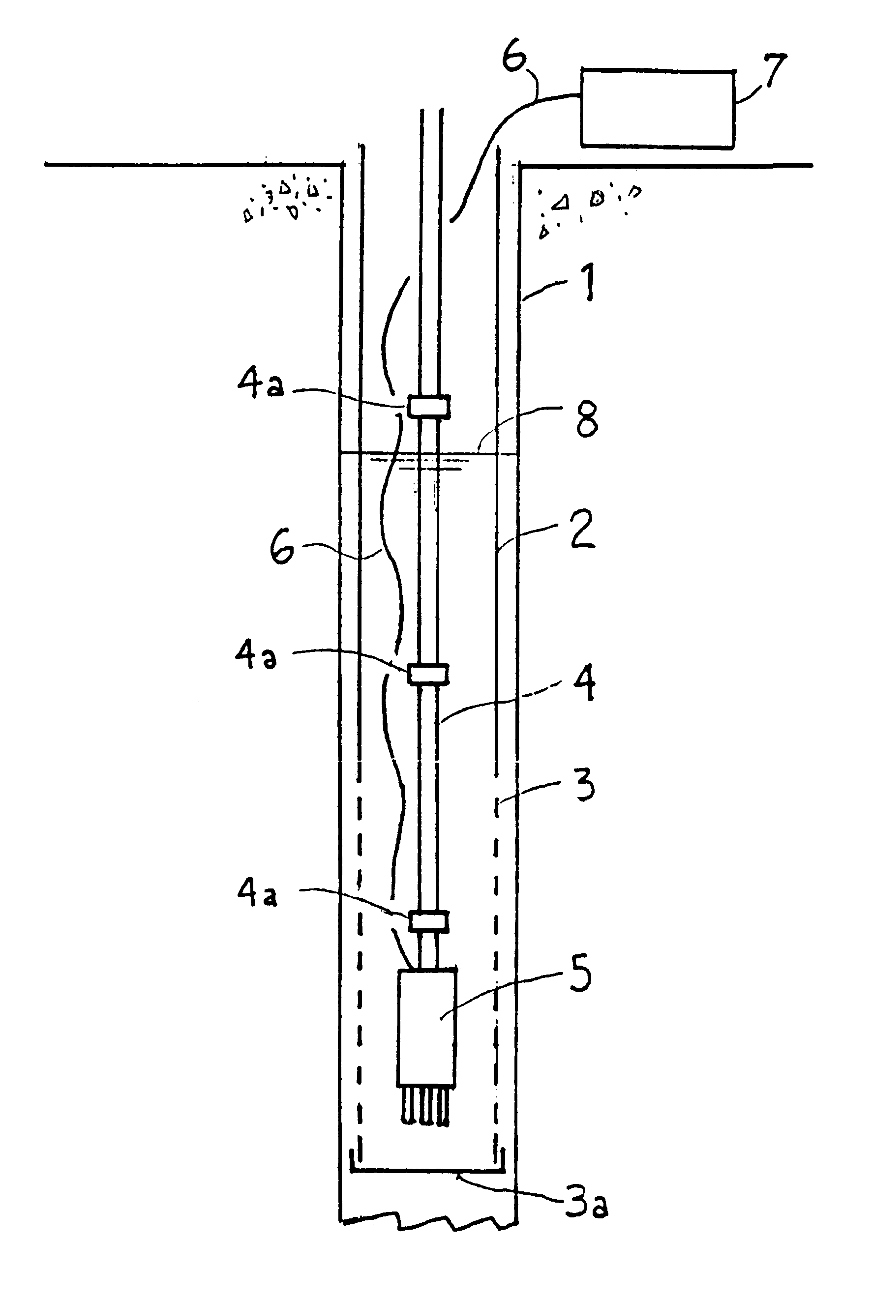
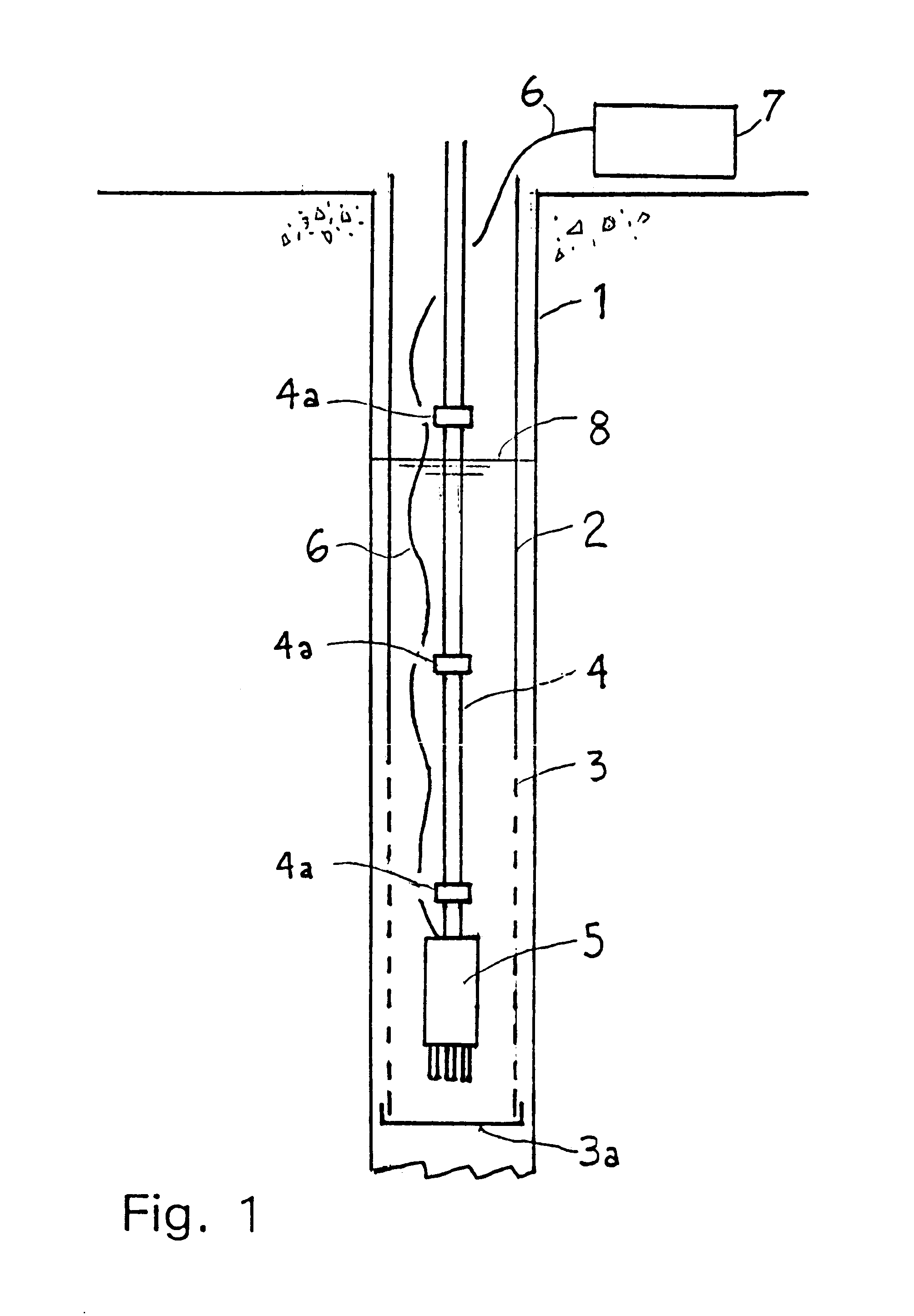
With reference to FIG. 1, there is provided a vertical cylindrical well shaft or borehole 1 into which is inserted a well casing 2 whose outer surface snugly fits into the well; for clarity, FIG. 1 does not show the closeness of the fit of the well casing in the well borehole. At the bottom of the casing 2, there is provided a slotted, perforated or screened section 3 which is immersed in the groundwater at the level of interest and which allows horizontal groundwater flow through the region within the casing in which monitoring probe including a heater and a plurality of temperature sensors are positioned. The casing is capped at its lower extremity by a cap 3a. A suspension system comprising hollow tubes 4, having affixed to its lower extremity a monitoring probe 5, is inserted into the casing 2 such that the monitoring probe 5 is immersed in the groundwater 8 at the level of interest for groundwater flow measurement. Electrical wiring interconnects the components of the probe 5, ...


PUM

PropertyMeasurementUnit
diameteraaaaaaaaaa
seepage velocitiesaaaaaaaaaa
power levelaaaaaaaaaa

Abstract

A probe for monitoring groundwater flow seepage velocity and direction has an electrical heater and a plurality of temperature sensors located equidistant from the heater. The probe with the heater and temperature sensors is lowered into a monitoring well and positioned so as to be immersed in the groundwater. Energy is sent to the heater, and the temperature response at the temperature sensors is measured and recorded. From the measured response to temperature, the groundwater flow velocity and direction are computed and recorded. The temperature sensors may be resistance temperature detectors, thermocouples, or any other state-of-the-art temperature sensing device.

Description

I. BACKGROUND OF THE INVENTION1. Field of InventionThis invention relates to improved apparatus and a method of measuring groundwater flow. More specifically, it relates to apparatus and a method of measuring groundwater flow at very low seepage velocities and direction by the introduction of heat into the groundwater and sensing the distribution of the heat with temperature sensors.2. Prior ArtThere are many methods and devices for measuring fluid flow in the prior art. For example, U.S. Pat. No. 3,498,127 discloses a method wherein an energy source, such as a heater, is immersed in a moving fluid and wherein changes in fluid properties, such as temperature, are used to detect and measure flow velocity and direction. U.S. Pat. No. 4,628,743 discloses a device wherein a heat pulse is injected into the flowing stream by a miniature thermistor and the detection of an electronic time derivative of temperature downstream triggers subsequent heat pulses, the pulse frequency being related...

Claims


Application Information

Patent Timeline
Patent Type & Authority Patents(United States)
IPC IPC(8): E21B47/10G01F1/684G01F1/68G01P5/10G01P5/12
CPCE21B47/1005G01F1/68G01F1/684G01P5/12E21B47/103
Inventor MORSE, JAMES S.WILLIAMS, CHRISTOPHER R.LAWSON, DANIEL E.GARFIELD, DONALD E.TANTILLO, THOMAS J.
Owner U S ARMY CORPS OF ENGINEERS AS REPRESENTED BY THE SEC OF THE AMRY
Why Eureka
Try Eureka