Liquid container

a liquid container and container body technology, applied in the field of liquid containers, can solve the problems of difficult mass production of conventional liquid containers, difficult to manufacture tubular bodies by molding, and difficult to mass-produce conventional liquid containers

Inactive Publication Date: 2001-05-08
KOTOBUKI & CO LTD
View PDF5 Cites 65 Cited by
  • Summary
  • Abstract
  • Description
  • Claims
  • Application Information

AI Technical Summary

Benefits of technology

The serrated gear teeth formed at the front end of the operation cylinder are brought into engagement with the ratchet gear tooth formed in the ratchet cylinder so that the user experiences a feeling of control in operating the serrated gear teeth and the ratchet gear tooth, and also the operation cylinder is prevented from rotating in the opposite direction (e.g., a direction in which the piston moves rearwardly). The ratchet gear teeth which can protrude / retract in the axial direction, as well as the insertion through hole pierced by the piston rod, are formed in the ratchet cylinder and manufacturing thereof is easy.
In addition, assembly can be implemented by inserting into the body from the rear of the body the unit comprising the ratchet cylinder, the piston, the piston rod, the piston rod guide and the operation cylinder all together. Thus, these components are modular (e.g., unitary) so that assembly can be implemented easily.
The body may has an inner step portion formed on an inner peripheral surface thereof and the ratchet cylinder may have an outer step portion for contact with the inner step portion of the body. The container may includes a rotation preventive structure on the body and the ratchet cylinder for preventing relative rotation between the body and the ratchet cylinder.
According to the present invention, the ratchet cylinder is preferably provided separately from the body so that not only ratchet gear teeth (which can protrude / retract in the axial direction) are formed at a rear end of the ratchet cylinder, but also a bore (into which a piston rod is inserted in a relatively unrotatable fashion) is formed. Thus, a liquid container can be provided which is excellent for molding, assembly mass production, and practical use,

Problems solved by technology

Therefore, it is difficult to manufacture the tubular body by molding.
Thus, assembly becomes difficult, and it is difficult to mass-produce the conventional liquid container.

Method used


Image

  • Liquid container
  • Liquid container
  • Liquid container

Examples


Embodiment Construction

Referring now to the drawings, and more particularly to FIGS. 1-5, there is shown a preferred embodiment of the structure according to the present invention.

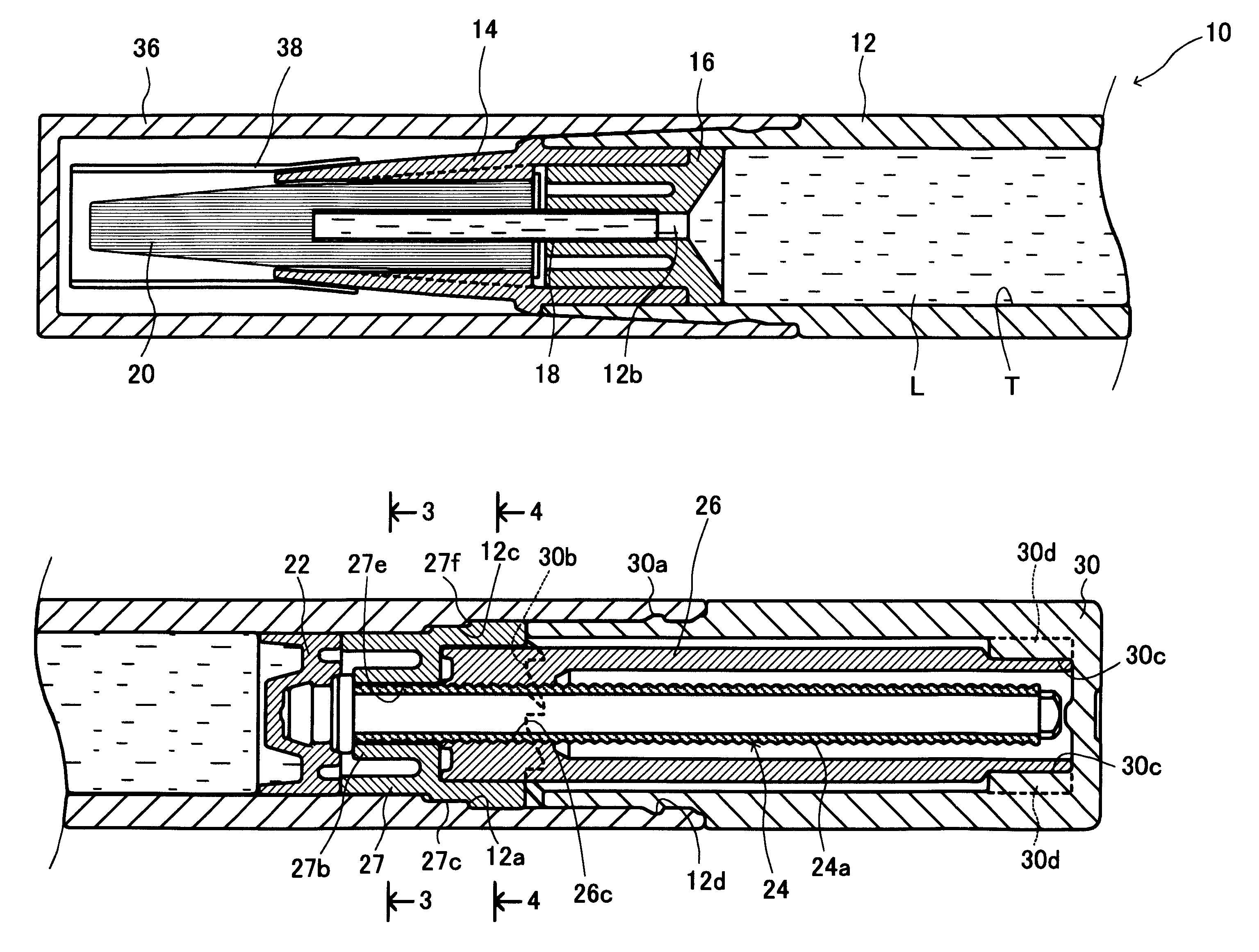
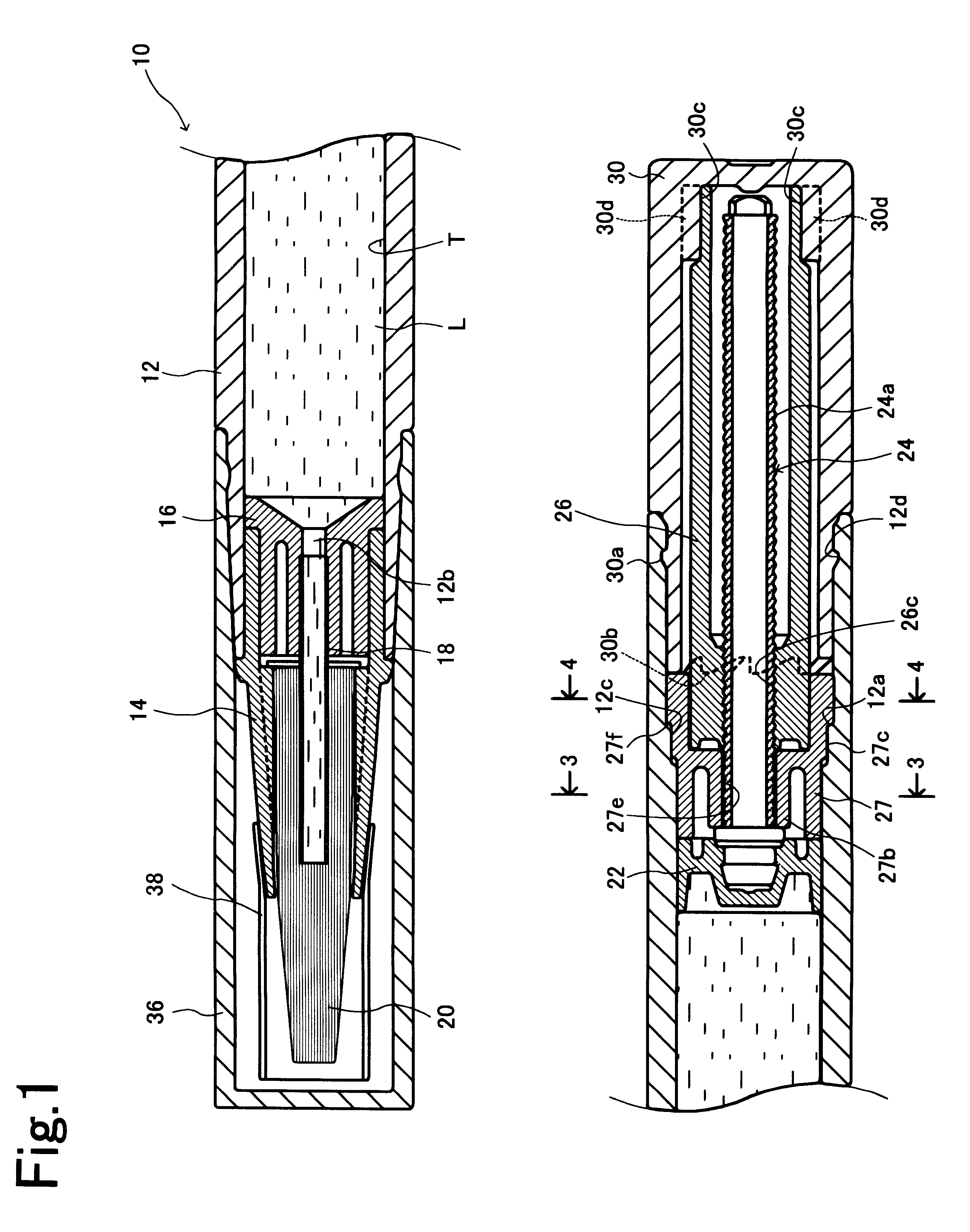
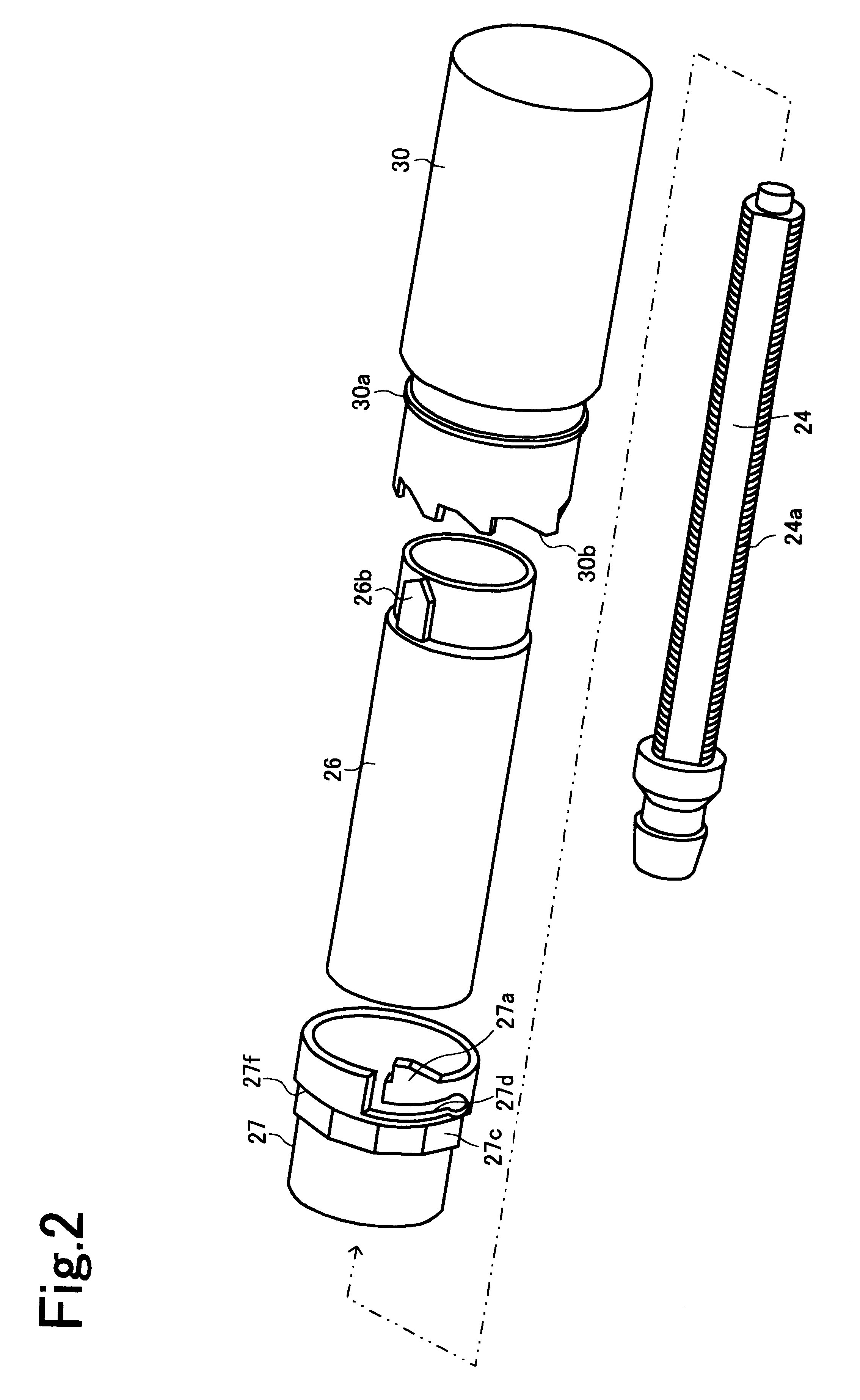
Referring to FIG. 1, a liquid container 10 includes a body 12 which has a tank portion T containing liquid L, for example, correction liquid, writing ink, cosmetic liquid, etc., and a liquid supplying port 12b. The liquid container 10 has a head part 14 fixed at the tip of the body 12, a pipe holder 16 fixed at the rear portion of the head part 14, a tip pipe 18 fixed to the pipe holder 16 so as to communicate with the liquid supplying port 12b, a brush (i e., liquid-applier member) 20, having a base fixed inside the head part 14, the tip of the tip pipe 18 being inserted into the base of the brush 20, a piston 22 slidably incorporated in the tank portion T, a piston rod 24 integrally connected to the piston 22 and extending rearwardly, the piston rod 24 having an external thread 24a provided on a periphery thereof, an operation...


PUM


Abstract

A liquid container includes a body having a tank portion housing liquid, and a liquid supply port at a front side thereof, a piston moving forward inside the tank portion, a piston rod being integrally connected to the piston and extending rearward, the piston rod having an external thread formed in a periphery thereof, an operation cylinder being attached to a rear part of the body in a relatively rotatable fashion, a piston rod guide being adapted to be rotated integrally with the operating cylinder, the piston rod guide having an internal thread hole which is engaged with the external thread of the piston rod, and a ratchet cylinder being fixed in the rear inside the body, the ratchet cylinder having a bore through which the piston rod is pierced in a relatively unrotatable fashion. The operation cylinder is formed with serrated gear teeth at a front end thereof, and the ratchet cylinder is formed with a ratchet gear tooth which is brought into engagement with the serrated gear teeth and adopted to be selectively protruded or retracted in an axial direction, at a rear end thereof.

Description

1. Field of the InventionThe present invention relates to a liquid container which houses liquid, such as cosmetic liquid, writing ink, correcting liquid, etc. and, more particularly, to a liquid container which has a liquid supply port at its tip.2. Description of the Related ArtA conventional container housing such kinds of liquid is shown, for example, by Japanese Utility Model Publication No. 6-14844. This conventional liquid container includes a tubular body having an applying liquid storage part formed inside, a screw rod disposed in a protruding fashion in a piston slidably fitted inside the storage part, and a rotation cylinder comprising an inner cylinder member and an outer cylinder member which are integrally bound. A ring protrusion and an engaging ratchet being elastic at the front portion in the axial direction are integrally formed on the outer cylinder member of the rotation cylinder. The ring protrusion is urged into and fitted to a ring groove at the rear end of th...

Claims


Application Information

Patent Timeline
Patent Type & Authority Patents(United States)
IPC IPC(8): B43K5/00B43K5/06A45D34/04B65D83/00
CPCB43K5/06
Inventor KAGEYAMA, HIDEHEI
Owner KOTOBUKI & CO LTD
Why Eureka
Try Eureka