Flotation device

a technology of a floating device and a flange is applied in the field of floating devices, which can solve the problems of inability to use hands, inability to manoeuvrability, and inability to use feet/legs for manoeuvring and propulsion, and achieve the effect of efficient human propulsion and minimising the risk of snagging the lower surfa

Inactive Publication Date: 2001-05-08
BODDY GRAEME JAMES
View PDF6 Cites 26 Cited by
  • Summary
  • Abstract
  • Description
  • Claims
  • Application Information

AI Technical Summary

Benefits of technology

It is an object of the present invention to provide a float with a hydrodynamically efficient underwater profile, capable of efficient human propulsion, using hands and/or legs, which secures the user in a semi-reclining position and whi

Problems solved by technology

However, all these known flotation means are configured for use in a specific manner and do not meet requirements addressed by the present invention.
Although the use of hands is a possible alternative, it is impractical to use feet/leg power for manoeuvring and propulsion.
Although the seat can be folded flat to facilitate overland transport, via attached shoulder straps, the float is primarily intended for flat-water use, in particular for fishing/hunting:--the seating position is high, relative to the hulls, and would be precarious for white-water sue, given the relatively short hulls.
In order to obtain sufficient stability to minimise the risk of capsize together with the associated structural requirements, such craft tend to be substantial, expensive, cumbersome and unwieldy.
In contrast to the kayaks/canoes, foot propulsion on catamarans is possible, but the width of the inflatable hulls and the height of the occupant above the water inhibit practical use of the hands and thus oars are generally utilised.
Again, foot propulsion is impractical.
A drawback of such designs is the difficulty in getting in and out of the tube (especially when suitable attired for fishing) both ashore and following a puncture in the air bladder whilst in water.
The seating position is hydrodynamically inefficient and exposes the user's lower torso to underwater hazards, thus making white-water use in shallow rivers impractical.
Neither of these floatation devices has an efficient hydrodynamic shape or is suitable for white-water use due to the risk of injury from underwater obstructions.
Ease of entry and exit from the water is again problematic.
This configuration prevents the efficient, unrestricted us

Method used


Image

  • Flotation device
  • Flotation device
  • Flotation device

Examples


first embodiment

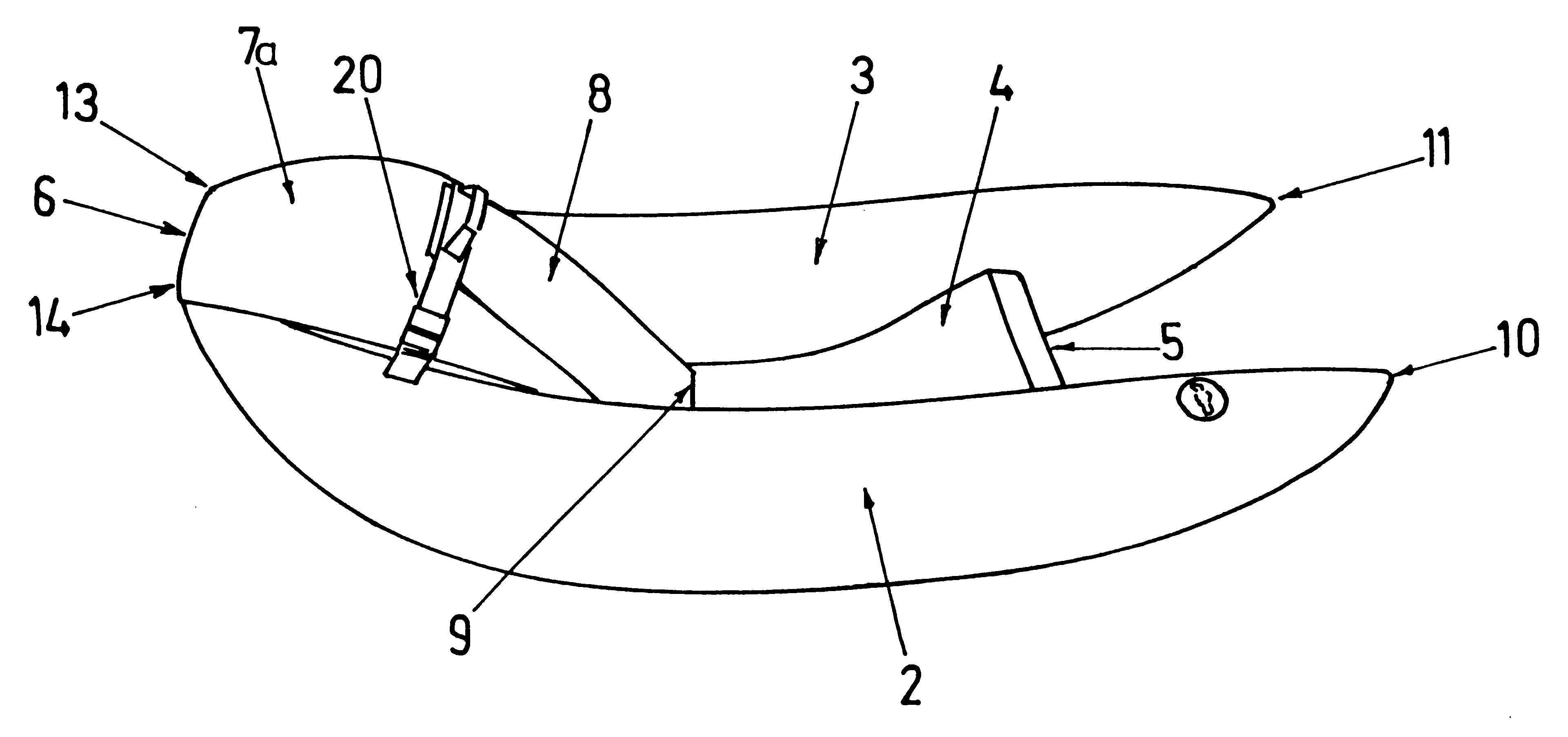
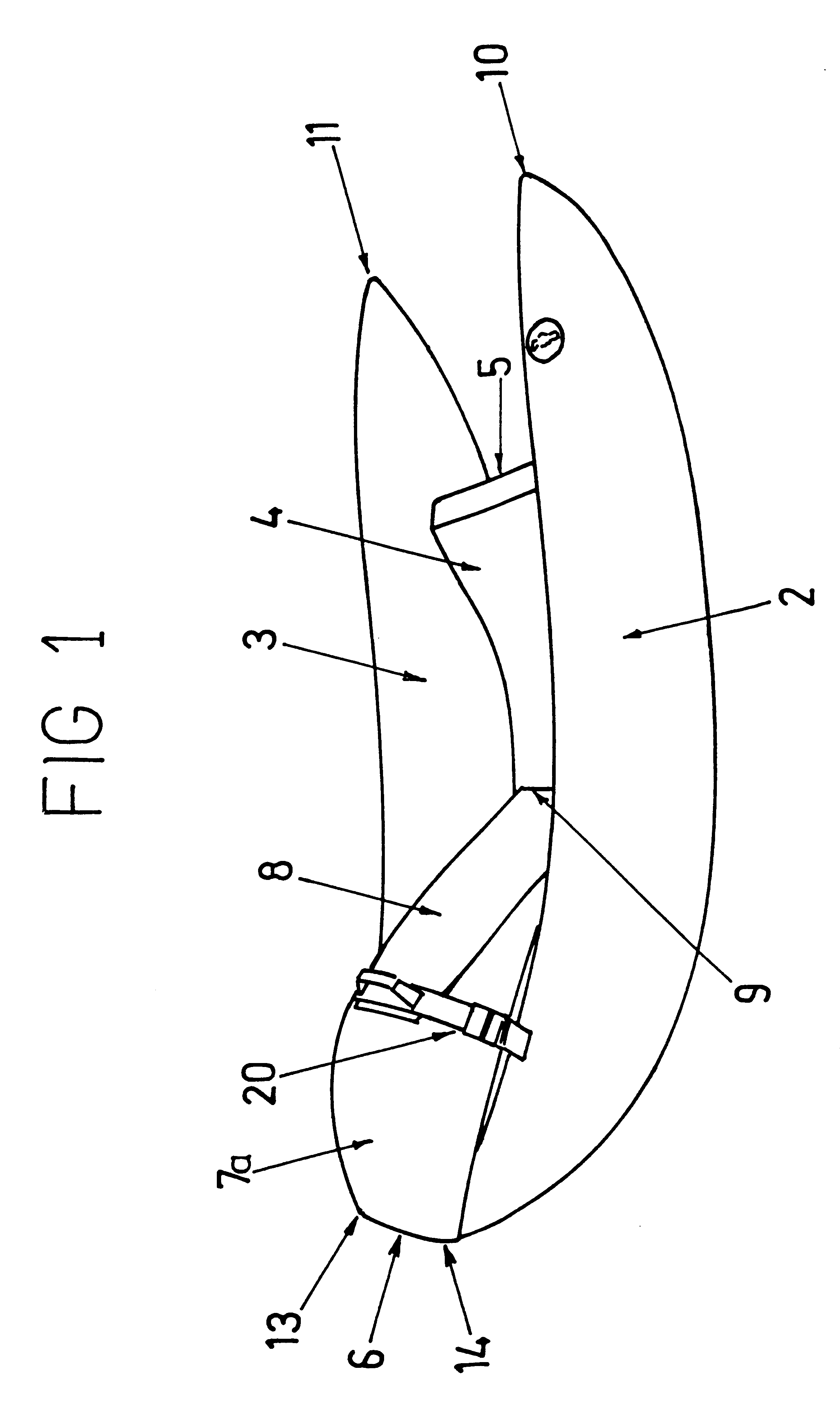
Referring to drawings 1-5, the U-shaped chair is comprised of two inflatable floats (2 & 3), a semi-rigid seat base (4), an adjustable seat-back (8), a bow hull floor section (12), a hull skin section (15a), an inflatable buoyancy bag (16) and a waterproof covering (7).

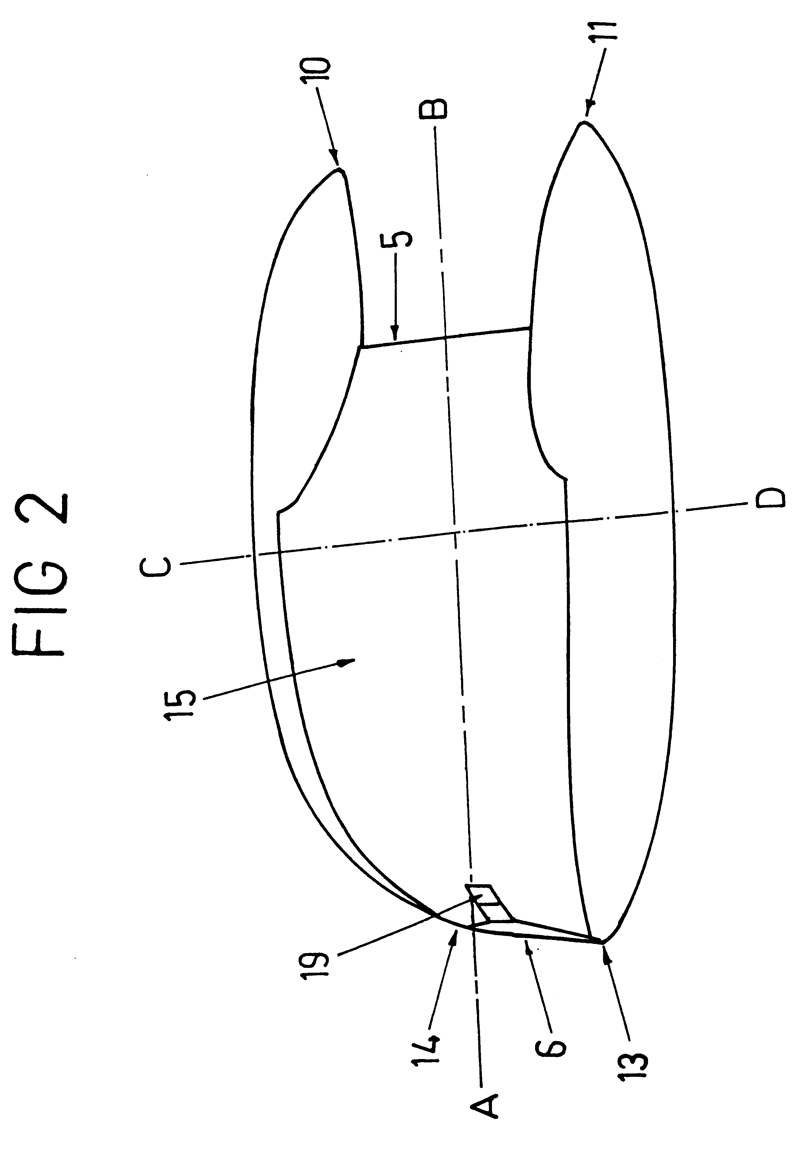
The two inflatable floats (2 & 3) are circular in cross-section and taper at both ends to conical points (10 & 11) at the tern and (13 & 14) at the bow. The longitudinal axes of the inflatable tubes (2 & 3) are orientated to converge towards the bow (6), (although they do not meet in this preferred embodiment) and are substantially parallel towards the stern.

The hull skin section (15a) is permanently fixed (e.g. stitched, glued or, heat-welded) to the floats (2 & 3). As shown in FIG. 4 the seat-base (4) and the bow hull floor section (12) are hinged together (to enable them to be dismantled and compactly folded) and are secured (e.g. zip, clips) to the aft-edge (5) of the hull skin section (15a) and pushed between (an...

fourth embodiment

In the preferred form of the fourth embodiment, the seat-back (8) is also integrally moulded with the floats / central section assembly (2a, 3a, 15) and is comprised of a near-rectangular section contoured to the shape of a user's back and upwardly inclined towards the bow from the intersection (9) with the seat-base (4).

In a fifth embodiment, shown in FIG. 3., the seat-back (8) may be formed as a distinct, adjustable, semi-rigid foam seat-back, which is zipped to the intersection (9) (as disclosed in the first preferred embodiment ). The volume between the seat back (8) and the bow-hull floor section (12) is filled by the removable, inflatable buoyancy bag (16) and / or cargo. In this embodiment, the use of inflatable buoyancy bag (16) and the possible adjustments to the seat-back (8) (including adjusting straps (20, 21) and all other related paraphernalia) correspond directly to the aforesaid description in the first embodiment

It has been found in practice that a reduced buoyancy embo...

sixth embodiment

The above comments assume the use of webbed gloves by the user, without which hand rolling would be far more difficult. The reduced cross-sectional area (and consequently a reduced width) of the floats (2,3) (as shown in FIG. 8) of a low buoyancy non-inflatable embodiment would produce a substantially parallel sided U-shaped hull (in plan view) from the stern to the region adjacent the user's chest / shoulders. FIG. 8 shows a plan view of the first preferred embodiment with the periphery of the low buoyancy sixth embodiment denoted by a dotted line (30). Provided the bow hull floor section (12) still maintained a hydrodynamically efficient side profile, a substantially straight, blunt-ended parallel-sided U-shape (as shown in FIG. 9) would be possible. However, the requirement would still exist for the user to be able to immerse (for paddling) their hand / slower arms whilst reclining on the seat back (8).

Any of the above embodiments (particularly the low buoyancy embodiment) may be use...


PUM


Abstract

A substantially rigid or semi-rigid chair suitable for white-water use with a hydrodynamically efficient underwater profile, capable of efficient human propulsion, using hands and/or legs, which supports the user in a semi-reclining position and which is sufficiently maneuvrable, in both forward and reverse direction, to enable the user to engage in white-water river use. In one embodiment, the chair consisting of two floats (2, 3), rigid/semi-rigid seat base (4), bow hull floor section (12) an adjustable seat back (8) and a waterproof covering (7). The floats (2, 3) are separated by a rigid/semi-rigid central section (15) comprised of the seat base (4), bow hull floor section (12) which extends from the bow (6) for a majority of the chair's length, and together with the seat back (8) providing a semi-reclining body position enabling the user to use hands and/or legs for propulsion/maneuvring.

Description

The present invention relates to an improved float or chair for aquatic use. The float or chair is specially useful for recreational use on white-water rivers, though it will be appreciated that the chair could readily be used on any other body of water.At present, personal flotation devices, fishing-floats, swimming-aids and white water canoes / catamarans are well known. However, all these known flotation means are configured for use in a specific manner and do not meet requirements addressed by the present invention.Known inflatable craft suitable for white-water use can be generally categorised as canoes / kayaks, catamarans, or rafts, although there is a degree of overlap with some hybrid craft.Typical inflatable canoes or kayaks are approximately symmetrical about their lateral and longitudinal axes, with enclosed sterns, and utilise oars or paddles for propulsion. Although the use of hands is a possible alternative, it is impractical to use feet / leg power for manoeuvring and prop...

Claims


Application Information

Patent Timeline
IPC IPC(8): B63B35/73B63B35/78B63B35/79
CPCB63B35/78B63B35/7906B63B34/52
Inventor BODDY, GRAEME JAMES
Owner BODDY GRAEME JAMES
Why Eureka
Try Eureka