Method and apparatus for providing dilution air to a blower motor

a technology of dilution air and hot water heater, which is applied in the direction of piston pumps, combustion types, combustion using lump and pulverulent fuel, etc., can solve the problems of affecting the overall efficiency of the blower and the ability to effectively cool the motor, and it is difficult to establish the negative pressure necessary to draw in the flue gas for expulsion from the water heater,

Inactive Publication Date: 2001-05-15
RBC MFG COPORATION
View PDF9 Cites 38 Cited by
  • Summary
  • Abstract
  • Description
  • Claims
  • Application Information

AI Technical Summary

Problems solved by technology

This approach to introducing cooling air into the blower has numerous problems which effect both the overall efficiency of the blower and the ability to effectively cool the motor.
By having the blower housing suspended over the flue pipe, it is very difficult to establish the negative pressure necessary to draw in the flue gases for expulsion from the water heater.
The lack of negative pressure results from the lack of a containment area or enclosure that enables the rotating impeller to generate the necessary negative pressure.
An additional problem encountered with the '099 patent design is the inability to control standby losses when there is no demand placed on the water heater.
With the flue open to the atmosphere, i.e, below the blower, absent blower activity, flue gases and heat generated during standby cannot be controlled.
A further problem is the inability to control the dilution air flow.
Altering impeller velocity, however, can have a negative effect on efficiency.
Although numerous blower housing designs have been developed to address motor cooling, none to date have the capability to provide a controlled amount of cooling air to the blower motor without the need for auxiliary fans attached to the motor.
None have devised a blower housing that is easy and cost-effective to manufacture such that the dilution air flow can be controlled to balance the need for exhaust gas expulsion and the need for motor cooling.
None have devised a blower housing that can accomplish these tasks as well as provide ease of assembly and disassembly for maintenance purposes.

Method used


Image

  • Method and apparatus for providing dilution air to a blower motor
  • Method and apparatus for providing dilution air to a blower motor
  • Method and apparatus for providing dilution air to a blower motor

Examples


Embodiment Construction

At the outset, the invention is described in its broadest overall aspects with a more detailed description following. A high efficiency water heater typically includes a combustion air inlet, a combustion chamber, a heat recovery section, a draft inducer and a combustion gas exhaust. When the water heater is in operation, the draft inducer or combustion blower creates a negative pressure or induces a draft in the water heater so air for combustion is drawn into the air inlet and then into the combustion chamber, where the air is mixed with a fuel such as natural gas for combustion or burning (i.e., the heat energy source). The heat energy of the combustion process is then extracted from the combustion or exhaust gases in the heat recovery section which also results in a reduction in the temperature of the combustion gases. For high efficiency water heaters, heat recovery is generally accomplished in two stages.

After passing through the heat recovery section of the water heater, the ...


PUM


Abstract

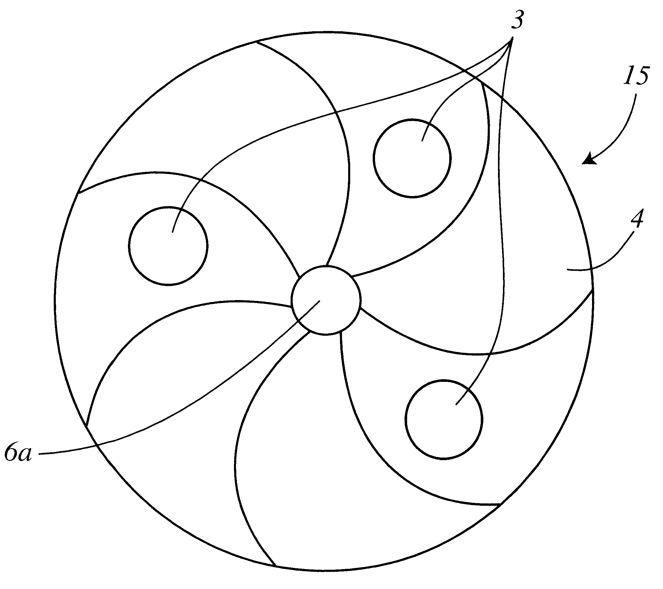
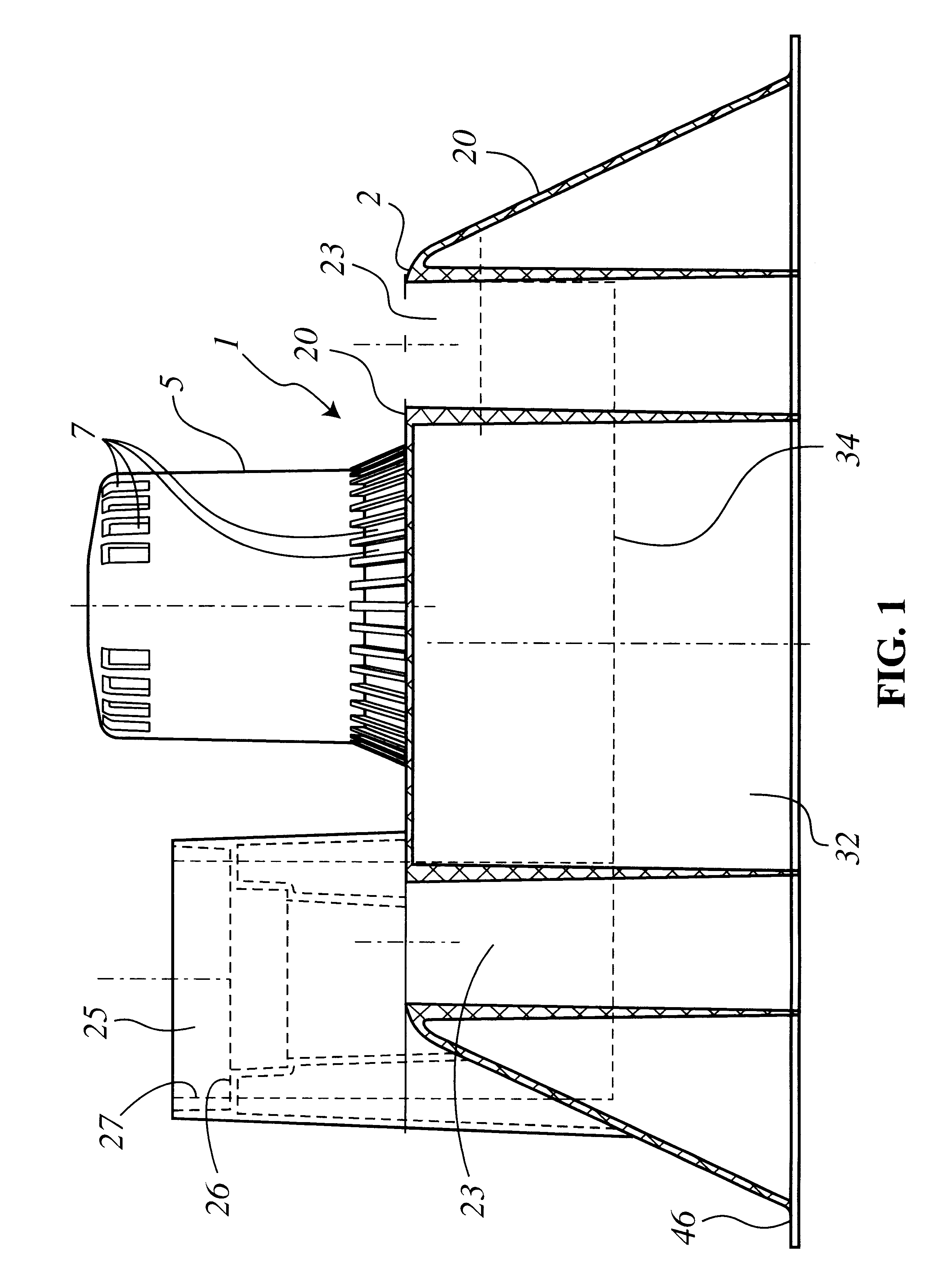
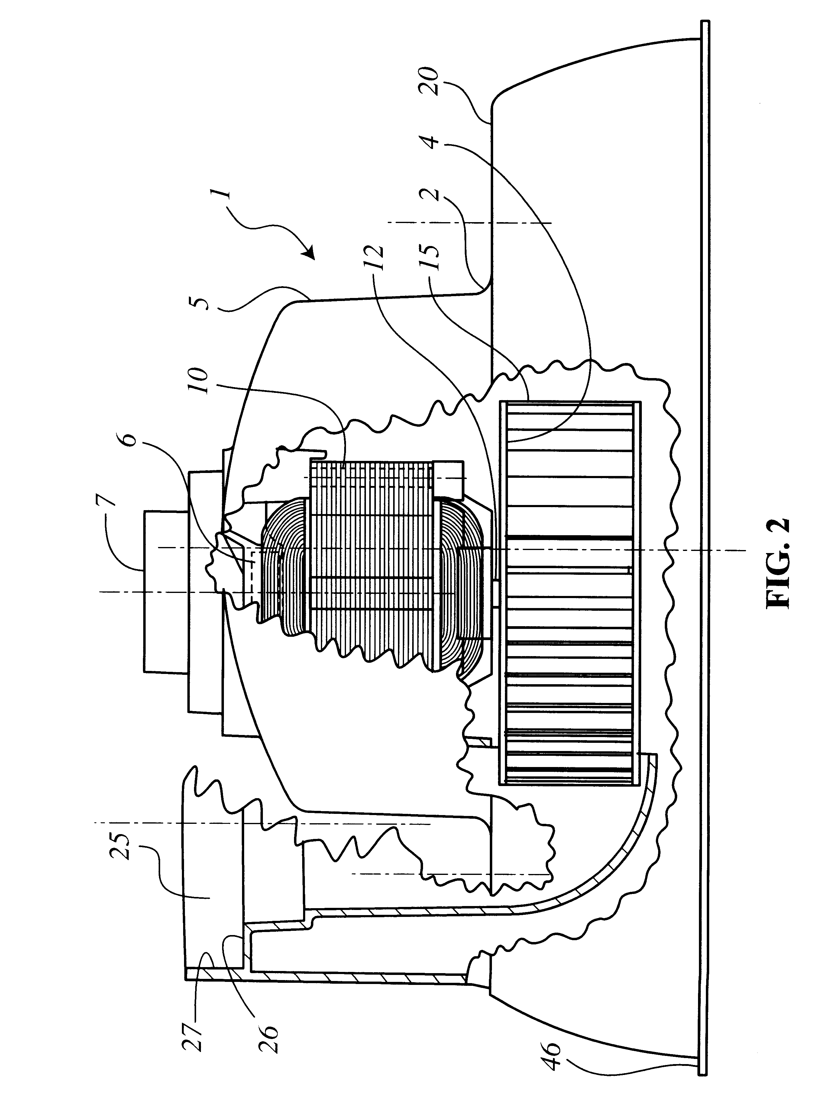
A blower is disclosed which has a housing that provides a means for drawing dilution air into a combined motor and impeller housing. The dilution air is drawn into a first chamber which houses the blower motor and is then drawn into the impeller chamber where the dilution air mixes with hot exhaust gases from a hot water heater to which the blower is attached. Apertures on a back plate of the impeller provide fluid communication between the motor chamber and the impeller chamber. The housing has walls which extend beyond a housing cover to form a skirt so that the attachment of the blower to a water heater top results in a third chamber being formed within which the water heat flue is situated.The combination of the skirt section, the housing cover and the top of the hot water heater comprise the third chamber which has at least one slot provided therein for drawing dilution air into the third chamber where the dilution air is mixed with the exhaust gases exiting the water heater flue. The mixed air and exhaust gas is drawn into the second chamber by the operating impeller where the mixture is further mixed with the dilution air drawn from the motor chamber into the housing. The mixed gases are then channeled out an outlet port formed in the blower housing.The invention eliminates the need for fans dedicated to cool the blower motor while providing the means for more effectively reducing the temperatures of the exhaust gases which exit the blower.

Description

1. Field of the InventionThis invention relates generally to draft inducers for hot water heaters. More particularly, the present invention relates to blower designs for cooling electric motors placed inside blower housings.2. Description of Related ArtTypical blower housing and motor assemblies, particularly with respect to centrifugal fans having radial-flow impellers, are configured with the motor being attached to an end of a circular or scroll-shaped blower housing. The motor's shaft extends axially into the housing where an impeller, confined by the blower housing, is attached to the motor shaft. The blower housing typically has one inlet and one outlet. Combustion gases are drawn into the housing by the rotating impeller which expels the gases through the outlet into a flue or similar avenue of exit.With respect to motor cooling, the gases that are forcibly moved through the housing by the impeller do not come into contact with the motor. Thus, blower activity does not in any...

Claims


Application Information

Patent Timeline
Patent Type & Authority Patents(United States)
IPC IPC(8): F04D25/08F04D25/02F23L17/00
CPCF04D25/082F23L17/005F04D29/5806
Inventor GATLEY, WILLIAM S.STEWART, DALE
Owner RBC MFG COPORATION
Why Eureka
Try Eureka