Dual-pressure steam injection partial-regeneration-cycle gas turbine system

a gas turbine and partial-regeneration technology, applied in steam engine plants, machines/engines, mechanical equipment, etc., can solve the problems of reduced steam flow to the mixer 10 and insufficient heat recovery

Inactive Publication Date: 2001-05-22
IHI POWER SYST CO LTD
View PDF4 Cites 38 Cited by
  • Summary
  • Abstract
  • Description
  • Claims
  • Application Information

AI Technical Summary

Problems solved by technology

However, if the pressure of the steam produced by the exhaust heat and which drives the mixer is solely increased, the flow of the steam to the mixer 10 is reduced, and as a result, the amount of heat recovered becomes insufficient.

Method used


Image

  • Dual-pressure steam injection partial-regeneration-cycle gas turbine system
  • Dual-pressure steam injection partial-regeneration-cycle gas turbine system
  • Dual-pressure steam injection partial-regeneration-cycle gas turbine system

Examples


Embodiment Construction

Preferred embodiments of the present invention are described below referring to the drawings. When the same parts appear in different figures, they are identified with the same part numbers.

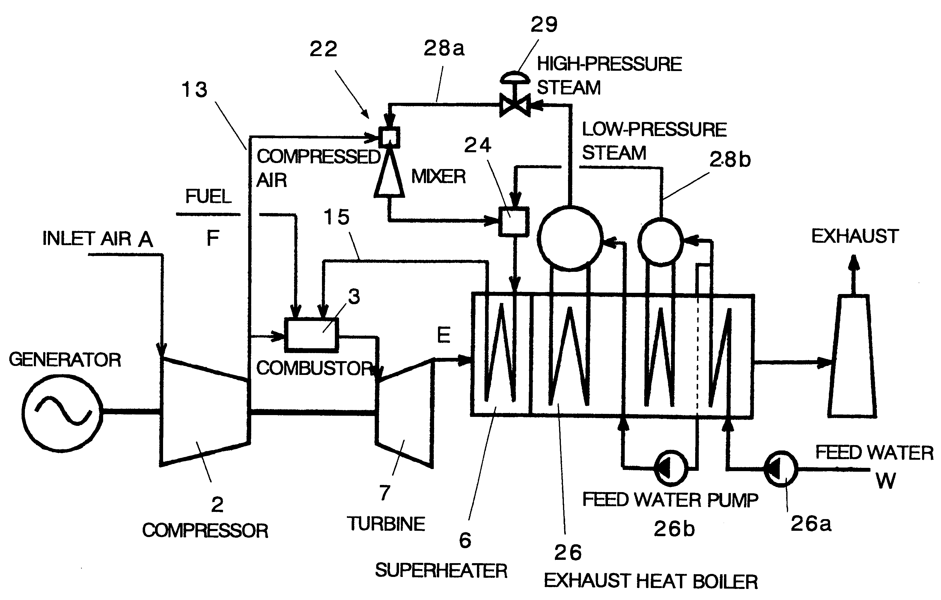
FIG. 6 is a diagram showing the general configuration of the dual-pressure steam-injection-type partial-regeneration-cycle gas turbine according to the present invention. In the figure, the partial-regeneration-cycle gas turbine system according to the present invention is provided with a gas turbine configured with a compressor 2 for compressing air A, a combustor 3 for burning a fuel F, and a turbine 7 driven by combustion gas E which drives the compressor 2, a superheater 6 located downstream of the turbine 7, an air line 13 for supplying part of the compressed air produced in the compressor 2 to the combustor and the rest to the mixer, and a mixed gas line 15 for transferring the air and steam mixture (gas mixture) to the combustor 3 via the superheater 6.

Other component devices of the partia...


PUM


Abstract

In the partial-regeneration cycle gas turbine system wherein part of the air compressed by a compressor 2 is extracted before a combustor 3, mixed with steam, and after the mixed gas is superheated by exhaust heat of a turbine, and the mixed gas is injected into the combustor, high-pressure steam is used as a fluid for driving a first mixer 22 that compresses extracted air, to increase the ratio of extracted air to steam, and then this mixed gas of extracted air and steam is further mixed with low-pressure steam from a low-pressure exhaust heat boiler, in a second mixer, and the mixture of gas is superheated in a superheater 6 by exhaust heat of the turbine, and injected into the combustor. Thus, the pressure of the driving steam can be raised, an exergy loss in an exhaust heat recovery portion can be reduced, and the efficiency of power generation can be increased without reducing the flow of generated steam.

Description

1. Technical Field of the InventionThe present invention relates to a gas turbine power generating system that generates electric power and steam, and more particularly to a binary-fluid-cycle gas turbine system wherein steam is injected into the gas turbine.2. Prior ArtA binary-fluid-cycle gas turbine system known in the prior art, wherein steam is injected into the gas turbine, is disclosed, for example, in the Japanese patent publication No. 34865, 1979 "Dual-action fluid heat engine."This binary-fluid-cycle gas turbine system (called the Cheng cycle from the name of the inventor) is typically as shown in FIG. 1. The system consists of a choke valve 1, compressor 2, combustion chamber 3, water treatment equipment 4, pump 5, heat exchanger 6, turbines 7 and 8, condenser 9, etc. In the system, air drawn in from the atmosphere is compressed by the compressor 2 and supplied to the combustion chamber 3, and fuel is burned in the compressed air to produce a high-temperature combustion ...

Claims


Application Information

Patent Timeline
Patent Type & Authority Patents(United States)
IPC IPC(8): F01K21/04F01K21/00F01K23/10F02C3/30F02C6/18F02C7/08
CPCF01K21/047F01K23/106Y02E20/16
Inventor UJI, SHIGEKAZU
Owner IHI POWER SYST CO LTD
Why Eureka
Try Eureka