Segmented heat sink

a heat sink and segmented technology, applied in the direction of laminated elements, semiconductor/solid-state device details, lighting and heating apparatus, etc., can solve the problems of insufficient heat dissipation of heat generated by devices, undesirable, exotic methods of cooling high-power electronic components, etc., to minimize the formation of high pressure and dissipate heat

Inactive Publication Date: 2001-05-22
AZAR KAVEH
View PDF34 Cites 31 Cited by
  • Summary
  • Abstract
  • Description
  • Claims
  • Application Information

AI Technical Summary

Benefits of technology

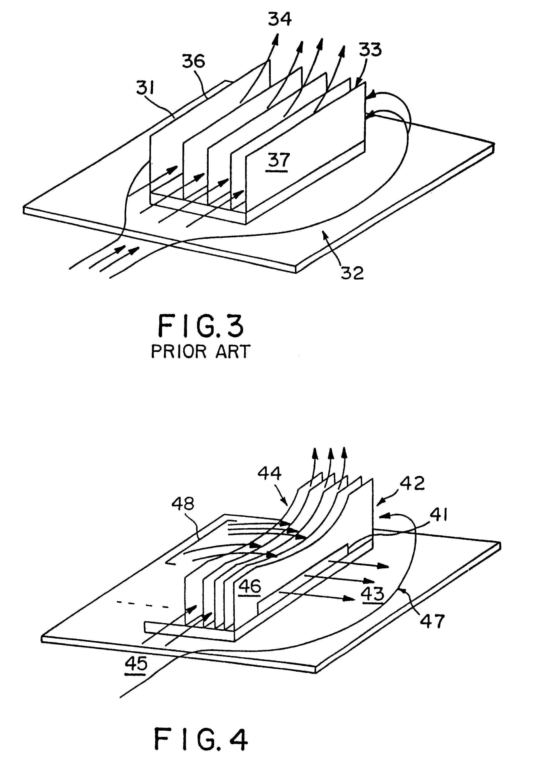
It is therefore the general object of the present invention to provide an improved heat exchanger for dissipating heat from a heat generating component, as well as a method of manufacturing the novel heat exchanger. The heat exchanger comprises a thermally conductive base in thermal communication with the component, a plurality of thermally conductive plate fins affixed to the base wherein the plate fins define a fin field and channels, and fluid control for controlling the flow of fluid within the fin field to minimize the formation of high pressure. Alternatively or in conjunction, the fluid control substantially prevents premature egress of fluid from the top of the fin field caused by the high pressure within the fin field.
It is a further object of the invention to utilize the low pressure created by flow by-pass to vent relatively high pressure fluid within the fin field. To this end, the fluid control comprises fluid communication between a portion of the channels and at least one side of the fin field. The fluid communication enables a portion of fluid within the fin field to be drawn out by the low pressure caused by the flow by-pass. In this way, the formation of high pressure within the fin field is substantially avoided. Suitable fluid communication in this embodiment includes slots, notches, orifices, or perforations through a fin, gaps or spaces along a plate fin, and combinations thereof.

Problems solved by technology

Finding suitable heat exchangers to adequately dissipate the heat generated by these components is a difficult task.
Exotic methods of cooling high-power electronic components, such as forced liquid cooling, are undesirable due to the high cost of implementation and maintenance in these systems.
Nevertheless, often these devices are inadequate to dissipate heat generated from high power electronics, although improvements are being made.
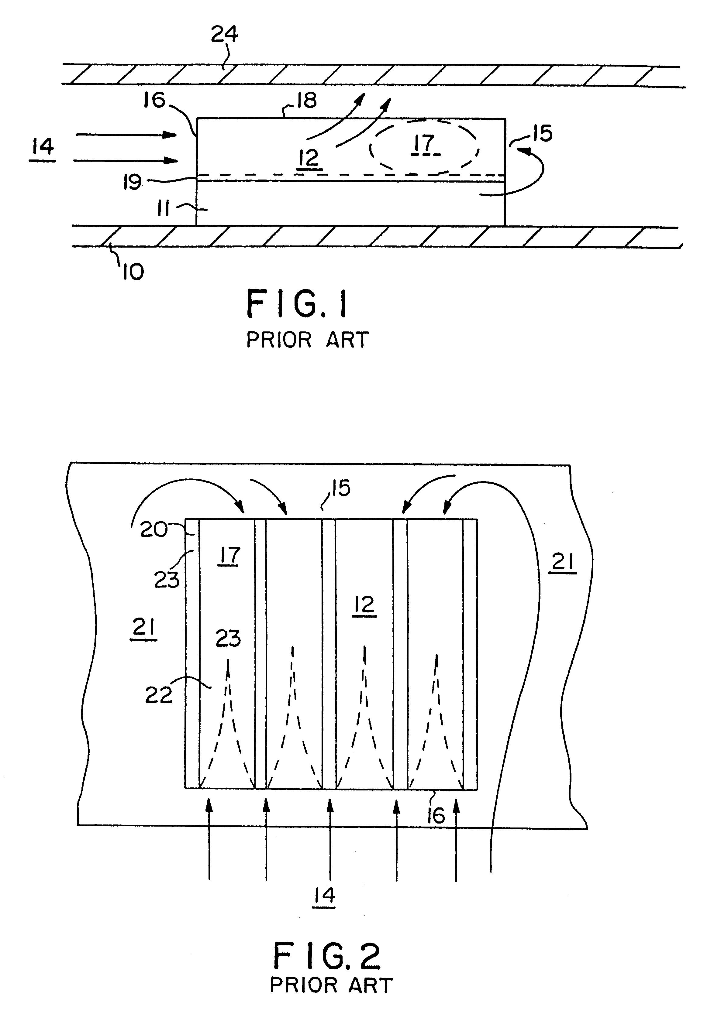
Although narrow channel heat exchangers significantly improve heat dissipation, they, like all other plate fin designs, suffer from boundary layer formation.
Additionally, the layer narrows the remaining channel available to fluid flow which further impedes fluid flow thereby compounding the problem.
The boundary layer therefore thickens as the fluid progresses down the channel contributing to high pressure within the fin field.
Unfortunately, however, such an approach leads to practical problems.
First, it is difficult, if not impossible, to extrude a plate fin having the desired surface irregularities.
Extrusion techniques are limited to producing lengthwise ridges (horizontal and vertical) which have limited ability to disrupt the boundary layer.
The applicant has found that high pressure in the fin field leads to inefficient heat transfer and premature egress of fluid from the fin field.

Method used


Image

  • Segmented heat sink
  • Segmented heat sink
  • Segmented heat sink

Examples


specific embodiments

Referring to FIGS. 5-33, specific embodiments of the present invention will now be considered in light of the principles above. These embodiments depict various configurations of the fluid control for (1) deterring the formation of high pressure, (2) reducing premature egress of fluid from the field, and / or (3) minimizing boundary layer formation. It should be understood that the particular flow control illustrated by these figures should not be construed to limit the scope of the invention, and may be interchanged and varied to form infinite combinations.

FIG. 5 shows a heat exchanger having a series of plate fins 51 with holes or perforations 52. The plate fins 51 are mounted to a base 54, and are further secured with bars 53 that traverse the plate fins across their top. It should be understood that such bars are optional in this embodiment as well as in the other embodiments disclosed herein. The plate fins 51 define channels 56 there between, and a plate fin field 57 and about. ...


PUM

PropertyMeasurementUnit
angleaaaaaaaaaa
angleaaaaaaaaaa
heataaaaaaaaaa

Abstract

A heat exchanger and a method of manufacturing the heat exchanger is disclosed for dissipating heat from a heat generating component. The heat exchanger comprises a thermally conductive base in thermal communication with the component, a plurality of thermally conductive plate fins affixed to the base wherein the plate fins define a fin field and channels, and fluid control for controlling the fluid flow within the fin field. The individual fins of the heat exchanger comprise a plurality of vertical segments extending from the base to the top area of the heat exchanger. The vertical segments are spaced apart by apertures. In an alternative embodiment, the horizontal width of the segments may vary to adjust the fluid flow through the heat exchanger. In conjunction with the above-outlined embodiments, the heat exchanger may comprise a fluid control feature for substantially preventing premature egress of fluid from a top region of the fin field caused by the high pressure region within the fin field.

Description

This invention relates generally to the cooling of heat-producing electronic components, and more particularly, to a heat exchanger having fluid control elements for deterring the formation of high pressure within the heat exchanger and / or reducing the premature egress of fluid from the heat exchanger caused by the high pressure.Effective dissipation of heat produced by electronic components is an important concern in optimizing circuitry performance. In addition to optimizing performance, effective heat dissipation also helps to prolong the useful life of those components. Heat dissipation is particularly important in the case of high-power electronic components, such as microprocessors and lasers, which generate a relatively high amount of heat in a relatively small area.Finding suitable heat exchangers to adequately dissipate the heat generated by these components is a difficult task. These components are typically used in systems housed within a cabinet having a fan mounted in t...

Claims


Application Information

Patent Timeline
Patent Type & Authority Patents(United States)
IPC IPC(8): F28F3/00F28F13/06F28F13/00F28F3/02H01L23/367H01L23/34H01L23/467H05K7/20
CPCF28F3/02F28F13/06H01L23/3672H01L23/467Y10T29/49915H01L2924/0002H01L2924/00F28F2215/08
Inventor AZAR, KAVEH
Owner AZAR KAVEH
Why Eureka
Try Eureka