RF power amplifier system having distributed modulation encoding

a power amplifier and modulation coding technology, applied in the field of am radio broadcasting, can solve problems such as output signal error and no reassignmen

Inactive Publication Date: 2001-05-22
GATESAIR
View PDF2 Cites 39 Cited by
  • Summary
  • Abstract
  • Description
  • Claims
  • Application Information

AI Technical Summary

Problems solved by technology

The difficulty with the multiple modulation encoder system is that if a power amplifier module or modulation encoder fails, no reassignment takes place.
Thus, if one of the power amplifiers in a first group controlled by the first modulation encoder fails, and if the failed module was supposed to be turned on, there will be an error in the output signal.

Method used


Image

  • RF power amplifier system having distributed modulation encoding
  • RF power amplifier system having distributed modulation encoding
  • RF power amplifier system having distributed modulation encoding

Examples


Embodiment Construction

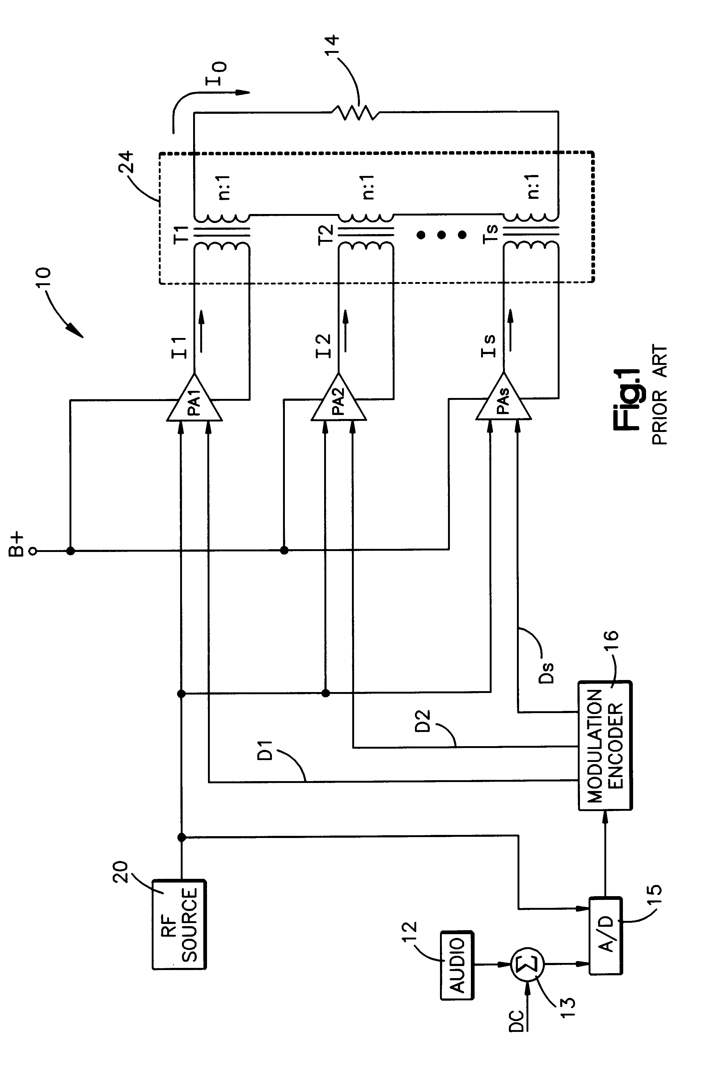
One application of the present invention is in conjunction with RF power amplifiers employed in an AM broadcast transmitter. An example of such a transmitter is presented in FIG. 1 and takes the form of a digital amplitude modulator such as that illustrated and described in the aforesaid U.S. Pat. No. 4,580,111 which is assigned to the same assignee as the present invention, the disclosure of which is herein incorporated by reference.

Referring now to FIG. 1, the amplitude modulator 10 is illustrated as receiving an input signal from input source 12 which may be the source of an audio signal. Modulator 10 generates an RF carrier signal which is amplitude modulated as a function of the amplitude of the input signal from source 12. The amplitude modulated carrier signal is provided to a load 14, which may take the form of an RF transmitting antenna. A modulation encoder 16 provides a plurality of digital control signals D1 through DS. The control signals are binary signals each having ...


PUM


Abstract

An RF power amplifier system is presented herein. It includes a plurality of RF power amplifier modules. At least two encoders are provided. Each encoder is associated with and controls the operation of some of the plurality of power amplifier modules. Each encoder is associated with different ones of the plurality of amplifier modules. An exciter receives an amplitude varying input signal and periodically provides a command signal to each of the modulation encoders and instructs that modulation encoder as to how many of its associated power amplifier modules are to be turned on as a function of the value of the input signal. Each modulation encoder responds to a received command signal and selects which of its associated power amplifiers to turn on.

Description

1. Technical FieldThis invention relates to the art of AM radio broadcasting and, more particularly, to a system having distributed modulation encoding for controlling the turn on of a plurality of power amplifier modules.2. Description of the Prior ArtThe H. I. Swanson U.S. Pat. No. 4,580,111 discloses an amplitude modulator for AM radio broadcasting wherein the modulator serves to generate amplitude modulated signals by selectively turning on and off a plurality of RF amplifier modules to produce amplitude modulation. The aforesaid Swanson patent has an encoder that supplies turn on commands to selected amplifier modules. In a system having a large number of power amplifiers, the power amplifiers are divided into groups with each group being provided with turn on signals from an associated modulation encoder. If, for example, each group includes 32 amplifier modules then the first modulation encoder will provide turn on module commands 0-31 if the module command is for turning on ...

Claims


Application Information

Patent Timeline
Patent Type & Authority Patents(United States)
IPC IPC(8): H03F3/20H03F3/217H03C1/36H03C1/00H04B1/04H04B1/00H03F1/52H03F3/68
CPCH03C1/36H03F3/2178H04B1/0483H04B1/00
Inventor DUELLO, WAYNE D.POSEY, DOUGLAS J.KORTE, THEODORE
Owner GATESAIR
Why Eureka
Try Eureka