Optical CDMA system using sub-band coding

a communication system and sub-band technology, applied in the field of optical communication systems, can solve the problems of inability to upgrade the network, the communication system only uses a small fraction of the available bandwidth, and the installation of optical fibers over long distances is expensiv

Inactive Publication Date: 2001-05-22
CODESTREAM TECH CORP
View PDF18 Cites 49 Cited by
  • Summary
  • Abstract
  • Description
  • Claims
  • Application Information

AI Technical Summary

Problems solved by technology

Installing optical fibers over long distances is expensive.
Additionally, conventional optical fiber or other optical communication networks utilize only a small fraction of the available bandwidth of the communication system.
No partial network upgrades are possible, which makes TDM systems less flexible than is desirable.
At least theoretically, the availability of appropriately tuned optical sources limit the number of users that can be supported by a WDM system.
As a more practical matter, the expense of WDM systems limits the application of this technology.
Lasers appropriate to the WDM video distribution system are individually expensive so that the requirements for 128 lasers having the desired operational characteristics make the overall system extremely expensive.
The expense of the syst

Method used


Image

  • Optical CDMA system using sub-band coding
  • Optical CDMA system using sub-band coding
  • Optical CDMA system using sub-band coding

Examples


first embodiment

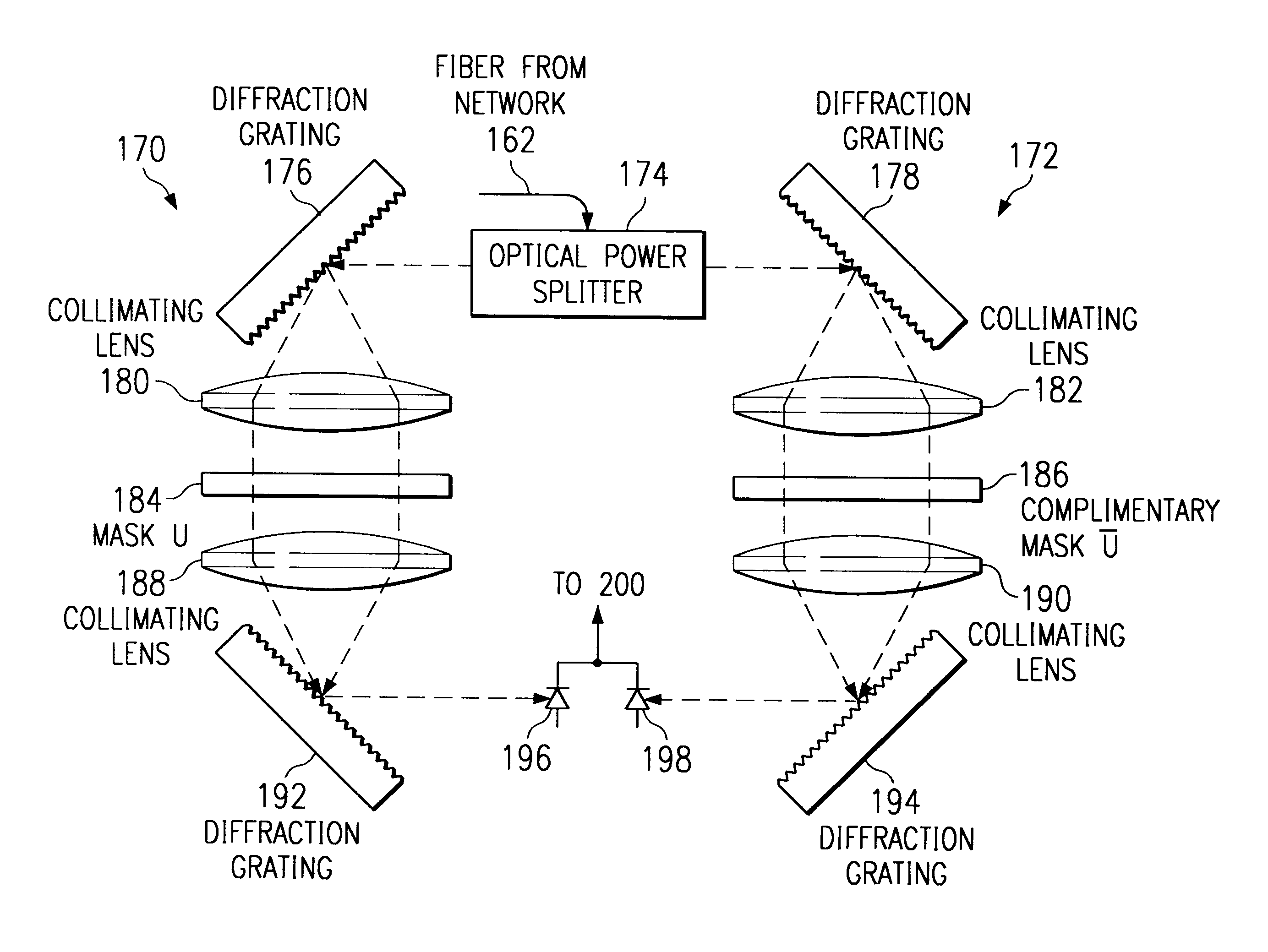
FIG. 7 is a block diagram of a decoder according to the present invention.

second embodiment

FIG. 8 is a block diagram of a decoder according to the present invention.

FIG. 9 is a sketch of a liquid crystal mask for use in a third embodiment of an encoder according to the present invention.

FIGS. 10A, B and C are continuous representations of discrete transparency functions for the mask of FIG. 9.

FIG. 11 is a graphical representation of a Fourier transform of light received from the fiber.

FIGS. 12A and B schematically illustrate an encoder and a decoder according to a third embodiment of the invention.

FIGS. 13A, B and C present a graphical representation of a mask and mask functions according to a next embodiment of the invention.

FIG. 14 schematically illustrates an apparatus for generating an array of N broad-spectrum optical sources having sufficient intensity to generate light beams for N channels of communication over a fiber using methods in accordance with the present invention.

FIG. 15 presents a different representation of the mask of FIG. 9.

FIGS. 16A and 16B illustrat...


PUM


Abstract

An optical fiber communications system using spread spectrum code division multiple access techniques to achieve better bandwidth utilization. A transmitting user in the system encodes the optical signal using a first coding mask, and a receiving user decodes the received signal using two decoding masks, all of the masks having lengths N. The first mask is divided into two sections of lengths N/2 each, one of the sections defining a first sub-code of length N/2, while the other section blocks light. Each of the second and third masks is also divided into two sections, which correspond to the two sections of the first mask. The section of the second mask corresponding to the coded section of the first mask has a second code that is identical to the first code, and the section of the second mask corresponding to the blocked section of the first mask is also blocked. The section of the third mask corresponding to coded section of the first mask has a third code that is complementary to the first code, and the section of the third mask corresponding to the blocked section of the first mask is also blocked. Some users on the system have masks in which the first of the two sections are blocked and the second of the two sections are coded, while other users have masks in which the second of the two sections are blocked and the first of the two sections are coded. The first codes used to code the encoding masks are selected from a set of unipolar codes that are derived from a set of balanced bipolar orthogonal codes.

Description

1. Field of the InventionThis invention relates to optical communication systems and, more particularly, to optical code-division multiple access communications systems that transmit data over optical fibers.2. Description of the Related ArtRecent years have seen rapidly expanding demands for communications bandwidth, resulting in the rise of technologies such as satellite communications, video programming distribution networks such as cable television, and spread-spectrum telephony including, for example, code-division multiple access telephony. Such technologies have become common and well integrated into everyday communications. Growing demand for communications bandwidth has brought significant investments in new communications technologies and in new communications infrastructure. For example, the cable television industry, telephone companies, Internet providers and various government entities have invested in long distance optical fiber networks and in equipment for fiber net...

Claims


Application Information

Patent Timeline
IPC IPC(8): H04J11/00H04J14/00G02F3/00H04J13/10H04J14/04H04J14/06
CPCH04J13/10H04K1/006H04K1/04H04J14/007H04B10/00H04B10/25
Inventor DUTT, BIRENDRANARAGHI, MANOUHERCHAN, JAMES K.
Owner CODESTREAM TECH CORP
Why Eureka
Try Eureka