Receiving circuit

a technology of receiving circuit and receiving circuit, applied in the field of receiving circuit, can solve the problems of difficulty in direct frequency conversion and direct demodulation, and the inability of the prior system to meet this requirement practically

Inactive Publication Date: 2001-05-22
PANASONIC CORP
View PDF11 Cites 65 Cited by
  • Summary
  • Abstract
  • Description
  • Claims
  • Application Information

AI Technical Summary

Problems solved by technology

That is, since the local oscillation frequency can not take the carrier frequency, in this kind of communication method difficulty is encountered in direct frequency conversion and direct demodulation.
For carrying out this method, fc+fo and fc-fo are obtainable by multiplication process of fc and fo through a mixer (frequency mixer), while both signals fc+fo and fc-fo coexist in an output More specifically, although the aforesaid process independently requires signals with the respective frequencies, the prior system can not practically satisfy this requirement.
The prior system essentially employs filters for the respective frequencies, while suffering a disadvantage that a carrier frequency for a desired signal is variable and hence the filters need to designed to cope with the frequency variations.

Method used


Image

  • Receiving circuit
  • Receiving circuit
  • Receiving circuit

Examples


tenth embodiment

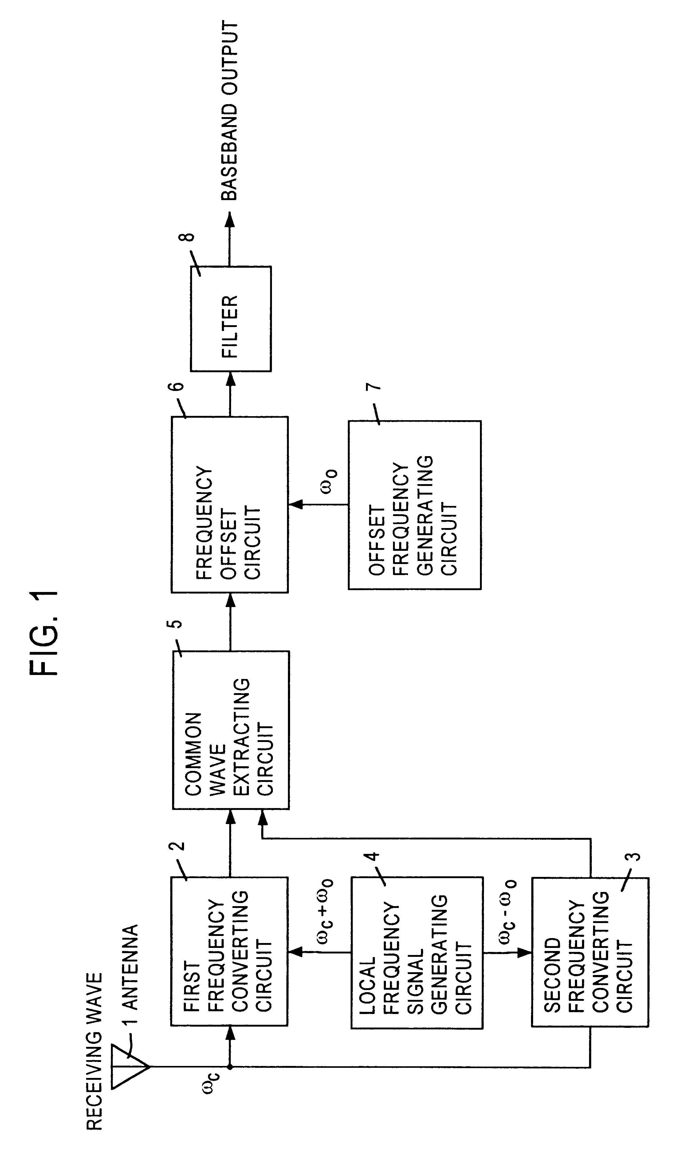
FIG. 10 is an illustration of an arrangement of a receiving circuit according to a tenth embodiment of this invention. In this embodiment, only the first frequency converting circuit 2 is provided for accepting the received signal from the antenna 1, as compared with the first embodiment shown in FIG. 1. After the frequency conversion by this first frequency converting circuit 2, a second frequency converting circuit 15, accepting a frequency corresponding to the inter-channel frequency 2.omega.o from the local frequency signal generating circuit 4B, provides a frequency-converted output in the side where the frequency conversion is not made by the first frequency converting circuit 2, thus ensuring two frequency-converted outputs necessary for the desired channel extraction by a common wave extracting circuit 5L.

Accordingly, in this embodiment, the outputs of the first and second frequency converting circuits 2 and 15 agree with the two outputs of the first and second frequency con...

eleventh embodiment

FIG. 11 is an illustration of an arrangement of a receiving circuit according to an eleventh embodiment of this invention. In this embodiment, as compared with the third embodiment shown in FIG. 3, the frequency converting circuit for accepting the received signal is effected with only the first frequency converting circuit 2 and further the quantizing means is constructed with only a bandpass filter 9C and an A / D converter 10C responsive to the output of the first frequency converting circuit 2. After the A / D conversion by the A / D converter 10C, a digital frequency converting circuit 16, accepting a frequency corresponding to the inter-channel frequency 2.omega.o from a digital frequency generating circuit 17, carries a digital frequency conversion, thus providing a frequency-converted output of the side where the frequency conversion is not made by the first frequency converting circuit 2 so as to obtain two frequency-converted digital outputs necessary for the extraction of the d...

twelfth embodiment

FIG. 12 is an illustration of an arrangement of a receiving circuit according to a twelfth embodiment of this invention. A feature of this embodiment is that as compared with the fifth embodiment shown in FIG. 5 the quadrature demodulating means for accepting the received signal is constructed with only one quadrature demodulating circuit 11 and the two outputs of the quadrature demodulating circuit 11 are frequency-converted in a frequency converting circuit 15A which accepts a frequency corresponding to the inter-channel frequency 2.omega.o from a local frequency signal generating circuit 4B, whereby the frequency-converted output of the side which is not quadrature-demodulated is obtainable to obtain two quadrature-demodulated outputs necessary for the extraction of the desired channel by first and second common wave extracting circuits 5N and SP.

Thus, according to this embodiment, the outputs of the quadrature demodulating circuit 11 and the frequency converting circuit 15A coin...


PUM


Abstract

A receiving circuit mainly available in a digital modulation type communication system having a plurality of channels, which is capable of reducing power in a receiving system, simplifying the circuit and reducing the power consumption. Upside and downside frequencies corresponding to a central value between channels are separately supplied from a local frequency signal generating circuit 4 to first and second frequency converting circuits 2, 3 so that two output signals are developed with respect to one of a desired wave, upside channel and downside channel. The desired wave present in common in the first and second frequency converting circuits 2, 3 is extracted in a common wave extracting circuit 5, and a frequency offset of omegao existing in the output of the common wave extracting circuit 5 is removed a frequency offset circuit 6 and further an unnecessary frequency component is filtered by a filter 8. In addition, the common wave extracting circuit 5 has transformers and, using its inductances, raises the difference between the common wave and the non-common wave within the circuit to more than two times that of a prior art.

Description

1. Field of the InventionThe present invention relates to a receiving circuit, and more particularly to a receiving circuit which permits simplification of its circuit arrangement and which further allows less power for a receiving system concurrent with reduction of power consumption.2. Description of the Prior ArtOne of important points needed for a receiving circuit in communications is to possibly reduce high-frequency circuit portions to thereby lessen a high power consumption factor, unstable operation factor and high manufacturing cost inherent in the high-frequency circuit, coupled with a space occupied by that circuit. These points are particularly important for mobile communication systems and others. For the reduction of the high-frequency circuit portions, a direct demodulation method has been proposed heretofore in terms of multiple frequency conversion and carrier frequency, thus accomplishing the direct conversion into a low frequency and the direct demodulation into ...

Claims


Application Information

Patent Timeline
Patent Type & Authority Patents(United States)
IPC IPC(8): H03D1/22H03D1/00H04B1/26H04B5/00H03D7/16H03D7/00H04B1/12
CPCH03D1/2245H04B1/0003H04B1/0032H04B1/26H04B5/0093H03F3/45475H03F3/50H03D7/165H03D2200/0047H03D2200/005H03D2200/0082H04B1/123H03F2200/537Y02D30/70
Inventor OHTA, GEN-ICHIROINOGAI, KAZUNORISASAKI, FUJIO
Owner PANASONIC CORP
Why Eureka
Try Eureka