Airbag payload landing system for damping landing impact forces on a flying payload

a technology for landing systems and airbags, which is applied in the direction of floating, pedestrian/occupant safety arrangements, emergency apparatus, etc., can solve the problems of adversely affecting the handling of the payload, the cross inclination of the payload is not sufficiently stabilized, etc., to achieve precise dropping of the load, the effect of minimizing the packing volume and the packing weight of the airbag

Inactive Publication Date: 2001-05-29
DAIMLER AG
View PDF8 Cites 63 Cited by
  • Summary
  • Abstract
  • Description
  • Claims
  • Application Information

AI Technical Summary

Benefits of technology

The embodiment of the airbag according to the invention has a simple construction without separation walls or intermediate walls in order to minimize the packing volume and the packing weight of the airbag. Further, the load will retain a substantially upright p

Problems solved by technology

Conventional airbags of this type have the disadvantage that they do not sufficiently stabilize the cross inclination of the payload when horizonta

Method used


Image

  • Airbag payload landing system for damping landing impact forces on a flying payload
  • Airbag payload landing system for damping landing impact forces on a flying payload
  • Airbag payload landing system for damping landing impact forces on a flying payload

Examples


Embodiment Construction

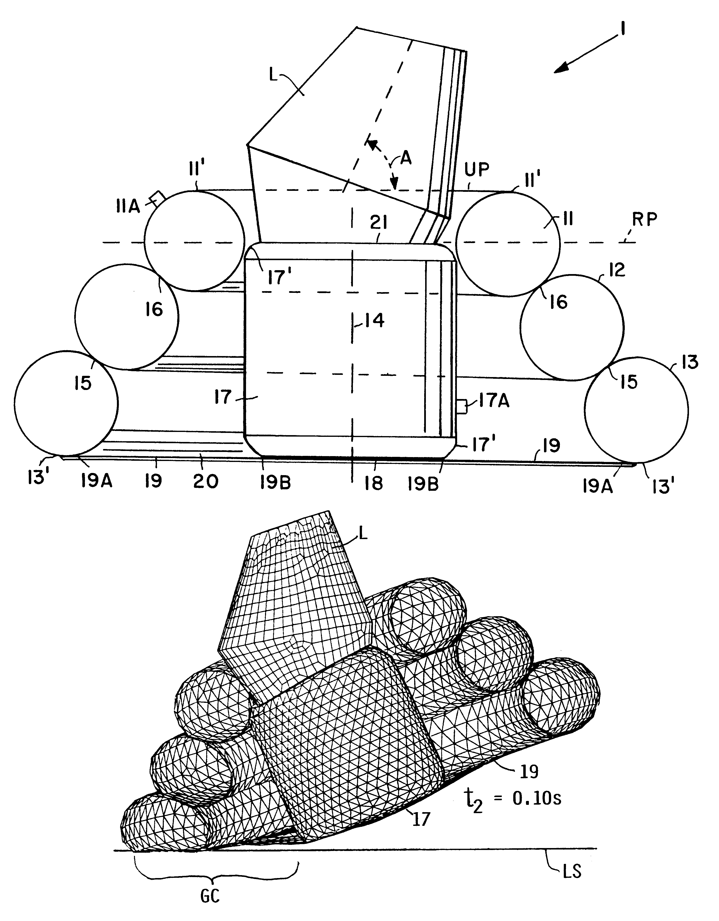
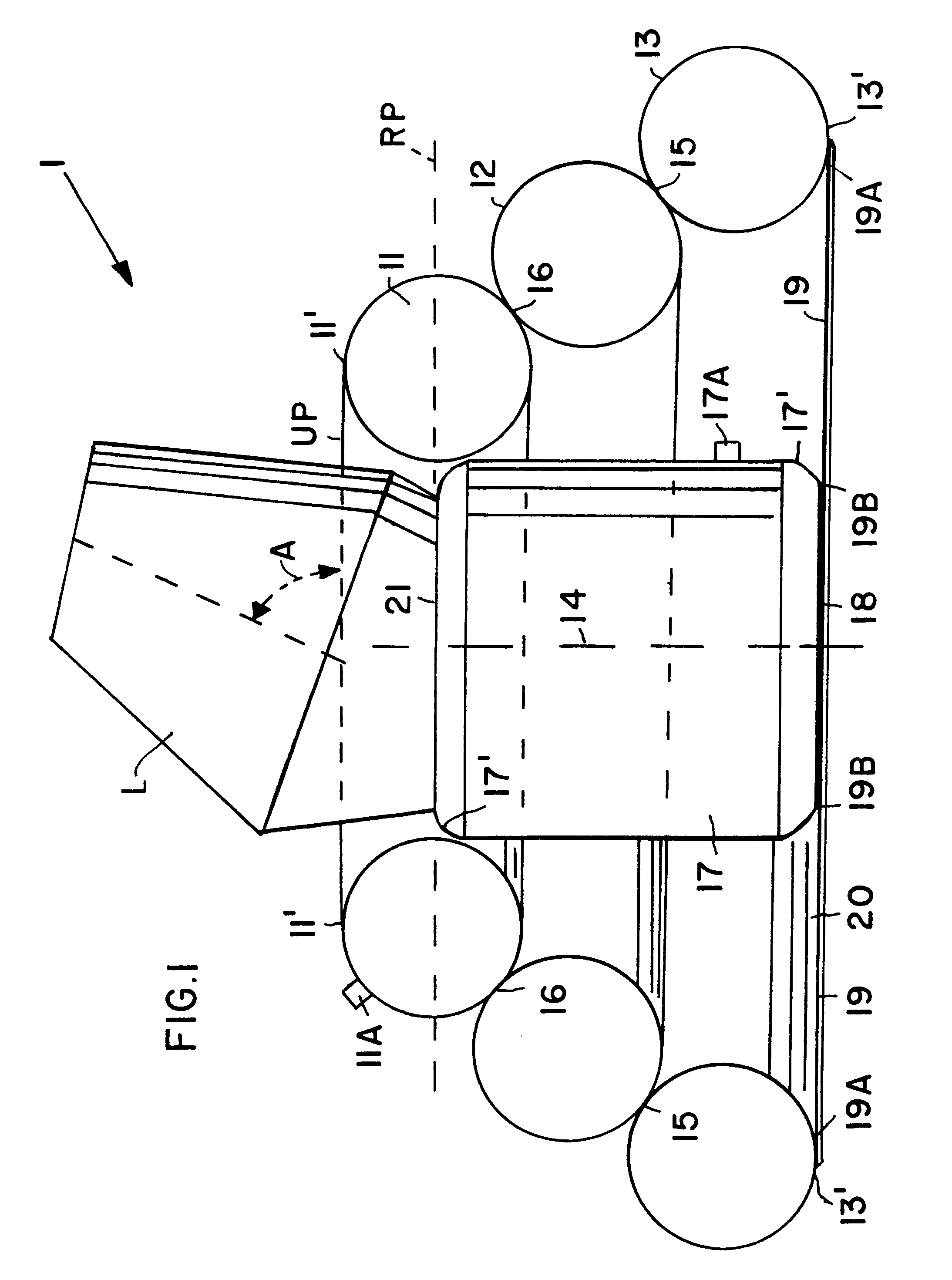
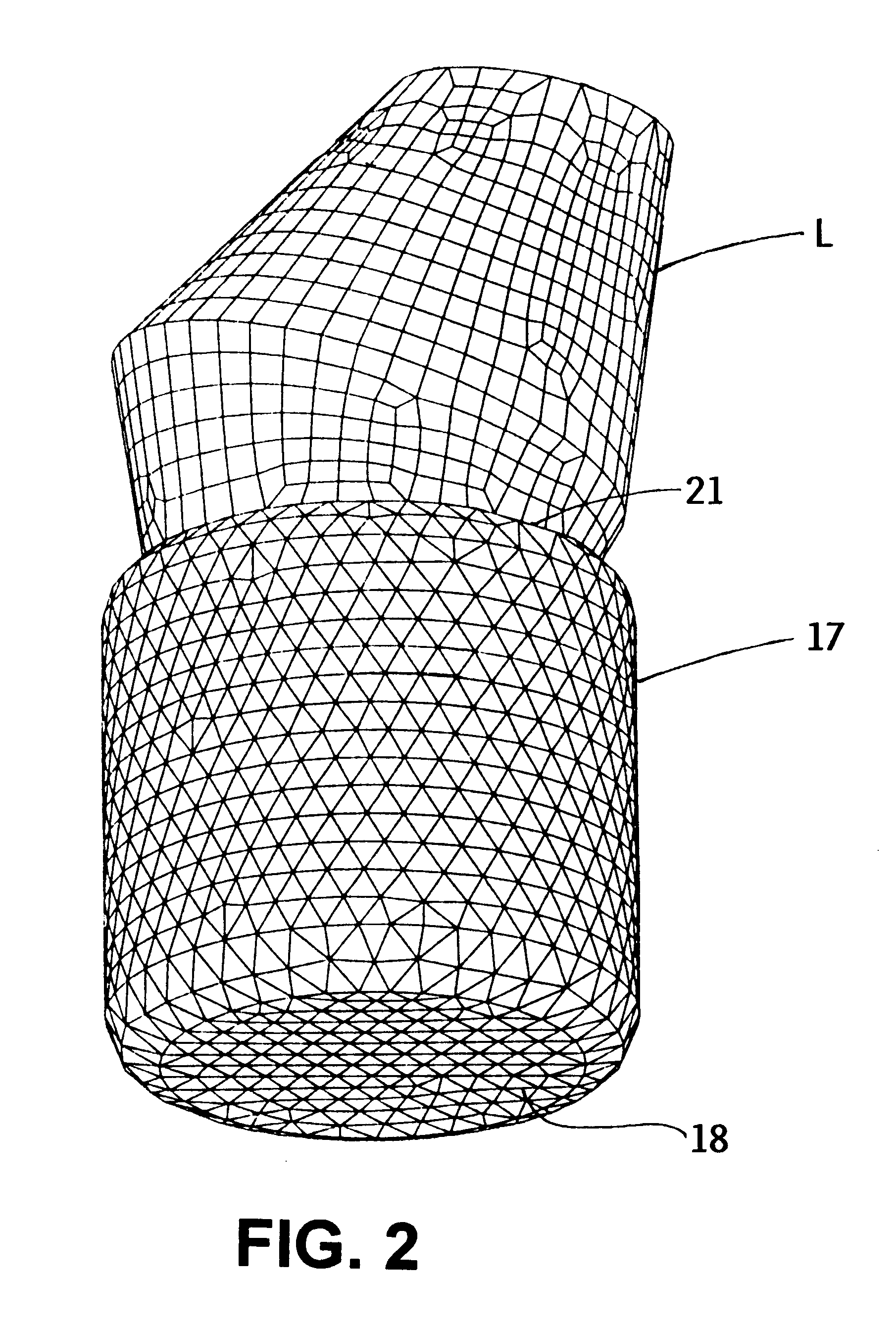
The airbag system 1 according to the invention comprises, for example, three airbag ring sections 11, 12, 13 stacked concentrically one above the other. The ring sections have ring diameters that diminish continuously from the bottom ring section 13 to the top ring section 11 along a central axis 14 corresponding to the Z-axis of a three-dimensional coordinate system 30. The ring section 13 of largest diameter is connected at 15 with the next smaller intermediate ring section 12. The intermediate ring section 12 is connected at 16 with the smallest diameter ring section 11. An airbag central section 17 is arranged concentrically to and inside the stack of ring sections 11, 12 and 13. This airbag central section 17 preferably has a substantially cylindrical configuration with a circular bottom surface 18 positioned in a plane tangent to the lowest ring line 13' of the lowest ring section 13. The cylindrical central section 17 has an upper preferably circular surface 21 positioned, as...


PUM


Abstract

An airbag configuration for braking the landing impact of flying payloads has a central airbag (17) and at least one torus ring (11, 12, 13) surrounding the central airbag. A payload (L) is attachable on the central airbag (17). A stabilizing device (19) is provided which extends from the lowermost portion of the at least one torus ring (11, 12, 13) to the central airbag (17). The central airbag provides primarily vertical braking of the landing impact while the torus ring provides primarily horizontal braking of the landing impact.

Description

PRIORITY CLAIMThis application is based on and claims the priority under 35 U.S.C. .sctn.119 of German Patent Application 198 37 329.5, filed on Aug. 18, 1998, the entire disclosure of which is incorporated herein by reference.The invention relates to an airbag payload landing system for braking or damping vertical and horizontal impact force components caused by a landing impact when a flying payload hits a landing surface.BACKGROUND INFORMATIONConventional airbags of this type have the disadvantage that they do not sufficiently stabilize the cross inclination of the payload when horizontal braking takes place. Further, conventional airbags have a relatively large volume so that their configuration adversely influences their handling. British Patent Publication 604,938 discloses a parachute landing gear for payloads to be dropped from an aircraft. The payload is mounted in a frame equipped with outrigger arms each carrying at its free end a foot for contacting the landing surface. ...

Claims


Application Information

Patent Timeline
IPC IPC(8): B64D1/00B64D1/14B60R21/34
CPCB64D1/14B64D2201/00
Inventor MENNE, STEFANKEERL, PETER NIKOLAUS
Owner DAIMLER AG
Why Eureka
Try Eureka