Portable gas burner

a gas burner and portable technology, applied in the field of portable gas burners, can solve the problems of easy fire and low heating effect in normal embodiments, and achieve the effect of convenient use and easy setting of fir

Inactive Publication Date: 2001-05-29
SSD INT
View PDF8 Cites 26 Cited by
  • Summary
  • Abstract
  • Description
  • Claims
  • Application Information

AI Technical Summary

Problems solved by technology

Modern gas burners work with an open flame that is directed towards the roof covering and might easily set fire to it.
So-called heat guns in which air is heated e.g. by an ele...

Method used


Image

  • Portable gas burner
  • Portable gas burner
  • Portable gas burner

Examples


first embodiment

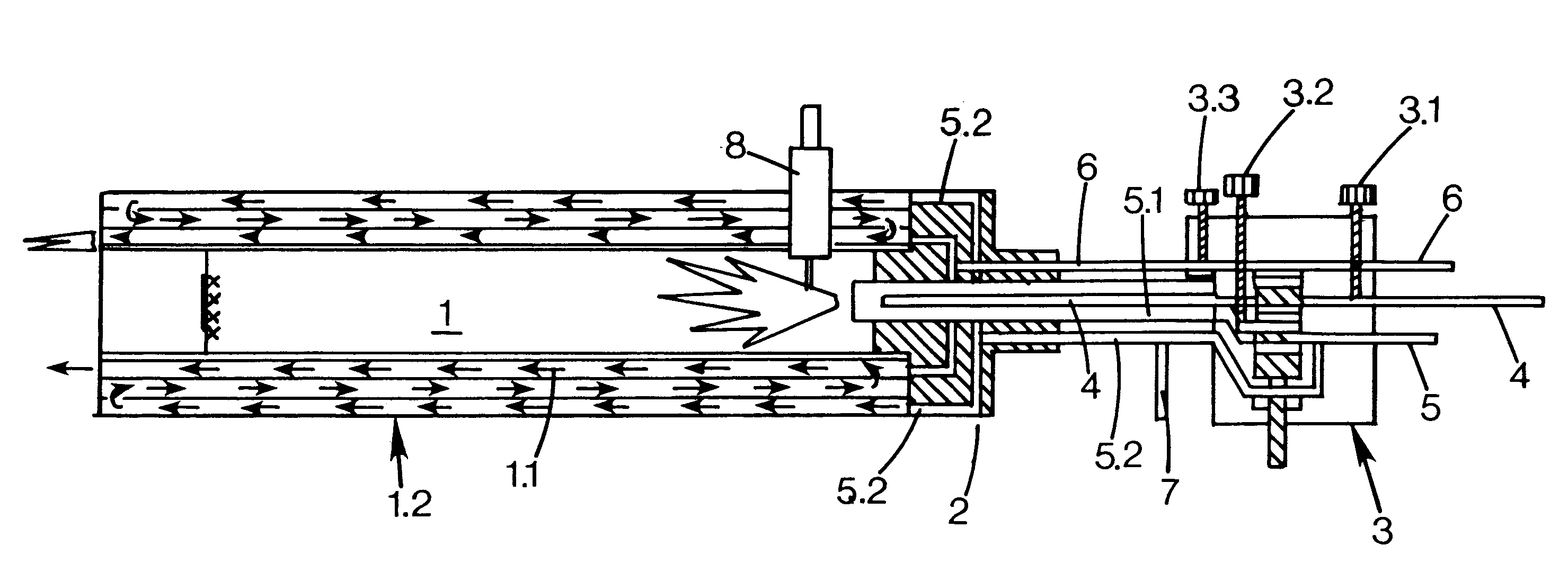
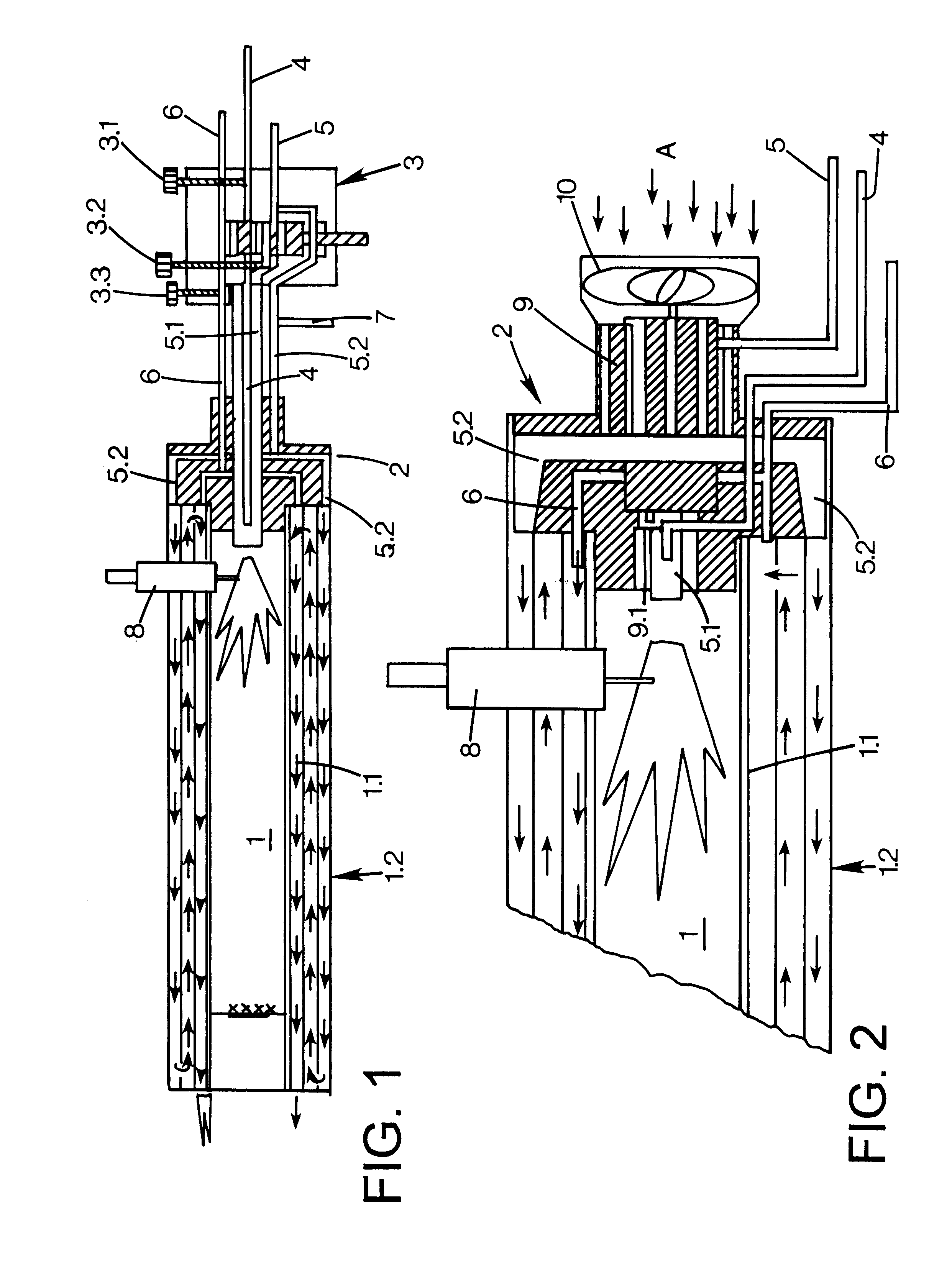
FIG. 1 shows schematically a burner according to the invention in a longitudinal section.

second embodiment

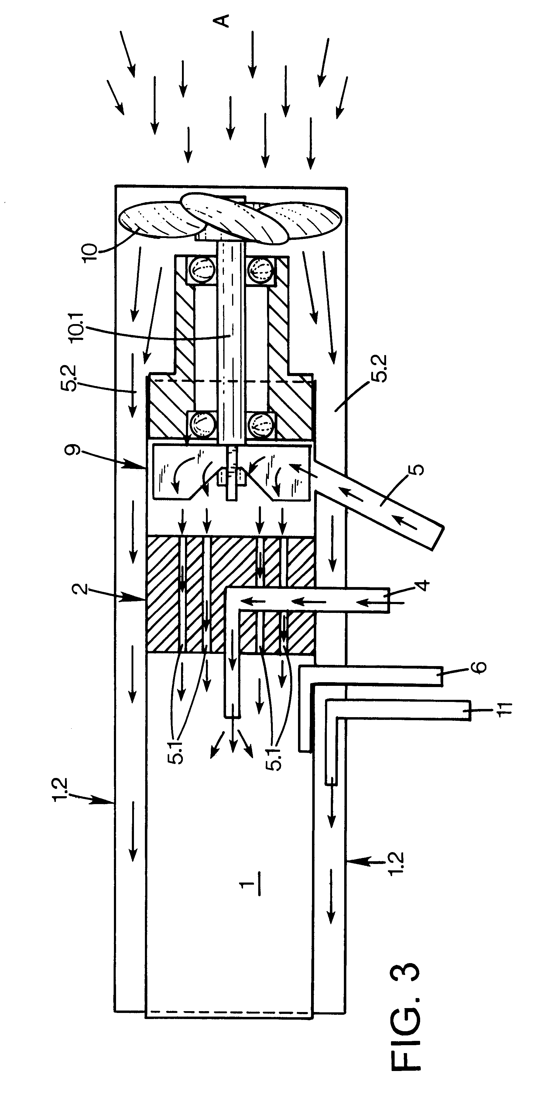
FIGS. 2 and 3 show schematically a burner according to the invention in a longitudinal section.

The burner in the first embodiment as shown in FIG. 1 comprises an elongated combustion chamber 1, formed from a metal pipe 1.1 that in its turn is attached into a tightening back 2. A cooling jacket 1.2 that comprises one or more cooling chambers encloses the combustion chamber 1. A number of conduits are connected to the back 2 via a valve housing 3. These conduits consist of a fuel gas conduit 4 that ends centrally inside the combustion chamber 1, a compressed air conduit 5 that partly is connected with the combustion chamber 1 via a combustion air conduit 5.1 and partly with the cooling jacket 1.2 via a cooling air conduit 5.2, and a conduit 6 for fire extinguishing medium and / or cooling medium such as nitrogen, carbon acid or water. In addition to these conduits a water conduit 7 for the generation of steam arranged in connection with the cooling air conduit 5.2 and connected to it be...


PUM


Abstract

Portable turner for combustion of a gaseous fuel comprising an elongated combustion chamber (1), the front end of which is open and the back end of which is closed with a back (2) and that is connected partly with a fuel gas conduit (4) and partly with a combustion air conduit (5.1), and that is enclosed by a concentric cooling jacket (1.2) for the flow of a cooling medium. The cooling jacket (12) shows an exhaust opening at the open front end of the combustion chamber (1) and is connected with a cooling air conduit (5.2) for the delivery of cooling air, that in its turn is connected with a compressed air source. The compressed air source may consist of a cooling blower (10) that is connected with an air motor (9) via a shaft (10.1) and that is fed with compressed air from a compressed air conduit (5).

Description

The present invention relates to a burner for combustion of a gaseous fuel, comprising an elongated combustion chamber, the front end of which is open and the back end of which is closed with a back. The combustion chamber is connected with partly a fuel gas conduit and partly a combustion conduit, in their turn being arranged to pass a valve mechanism for control of the mixture of gas and combustion air.BACKGROUND TECHNICSBurners of the kind described in the preamble may be found in stationary combustion plants where the combustion chamber is located inside e.g. a central heater. The combustion gases, generated by combustion in the combustion chamber, are arranged to be absorbed by the surrounding walls of the combustion chamber or by tubes, if any, through which the combustion gases flow which then are diverted via an exhaust pipe and e.g. through a chimney.In order to use a burner / heater according to the preamble for other purposes than e.g. for heating of water and generation of...

Claims


Application Information

Patent Timeline
IPC IPC(8): F23M5/08F23D14/22F23D14/00F23D14/34F23D14/32F23M5/00
CPCF23D14/22F23D14/32F23D14/34F23M5/085F23C2900/03005Y02E20/344
Inventor SARKINEN, DAVID
Owner SSD INT
Why Eureka
Try Eureka