
Electromagnetic interference grouping clamp

a technology of electromagnetic interference and clamping clamp, which is applied in the field of clamp, can solve the problems of unsightly hose clamp, unprofessional appearance, and low efficiency of hose clamp

Inactive Publication Date: 2001-06-05
LUCENT TECH INC
View PDF14 Cites 35 Cited by
  • Summary
  • Abstract
  • Description
  • Claims
  • Application Information

AI Technical Summary

Benefits of technology

It is an object of the present invention to provide a clamp which solves one or more of the drawbacks of the background art's grounding clamp and which also offers advantages outside the grounding environment.

Problems solved by technology

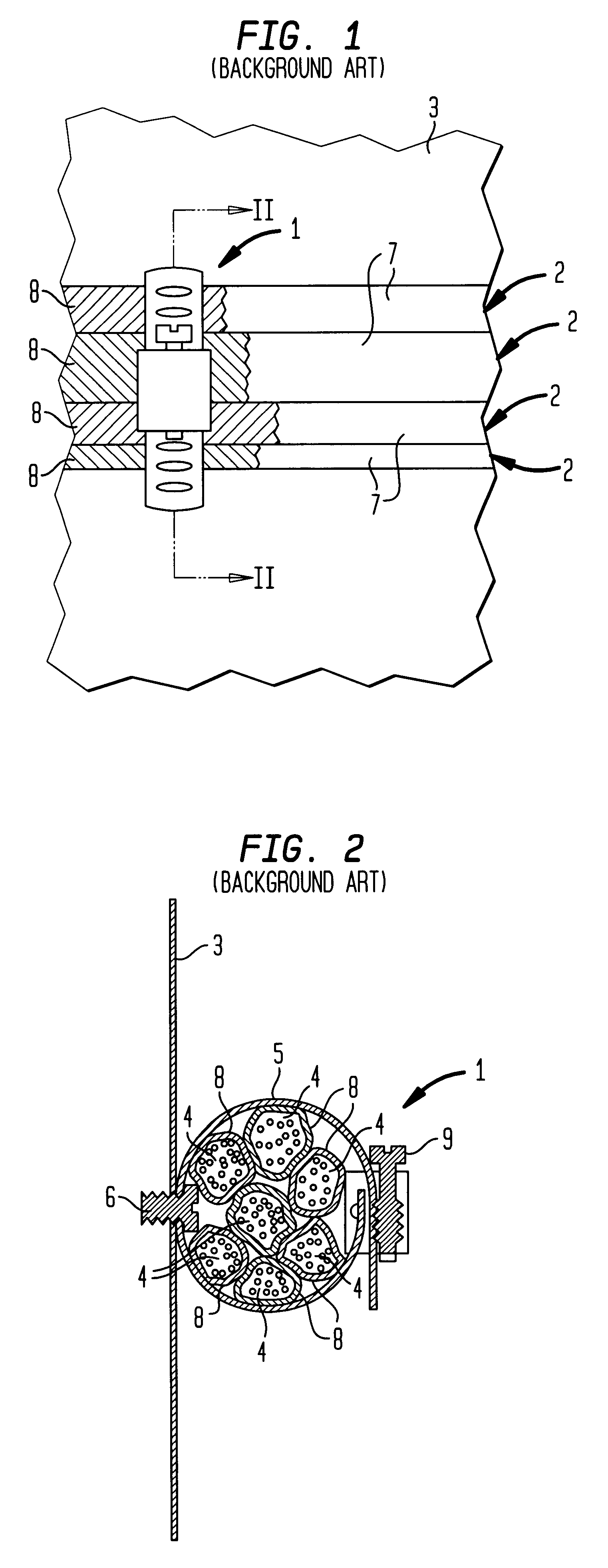
First, under-tightening of the tightening screw 9 can lead to play between the shielding layers 8 and result in noisy grounding.
A second drawback of the background art's hose clamp is that the number of shielded cables 2 to be connected to the grounded chassis 3 can vary between applications.
A third drawback of the background art's hose clamp is its unsightly, unprofessional appearance.
A simple hose clamp may not instill confidence in the owners and operators of the costly equipment, that competent and reliable components have been used in the construction of the electrical equipment.

Method used


Image

  • Electromagnetic interference grouping clamp
  • Electromagnetic interference grouping clamp
  • Electromagnetic interference grouping clamp

Examples


Embodiment Construction

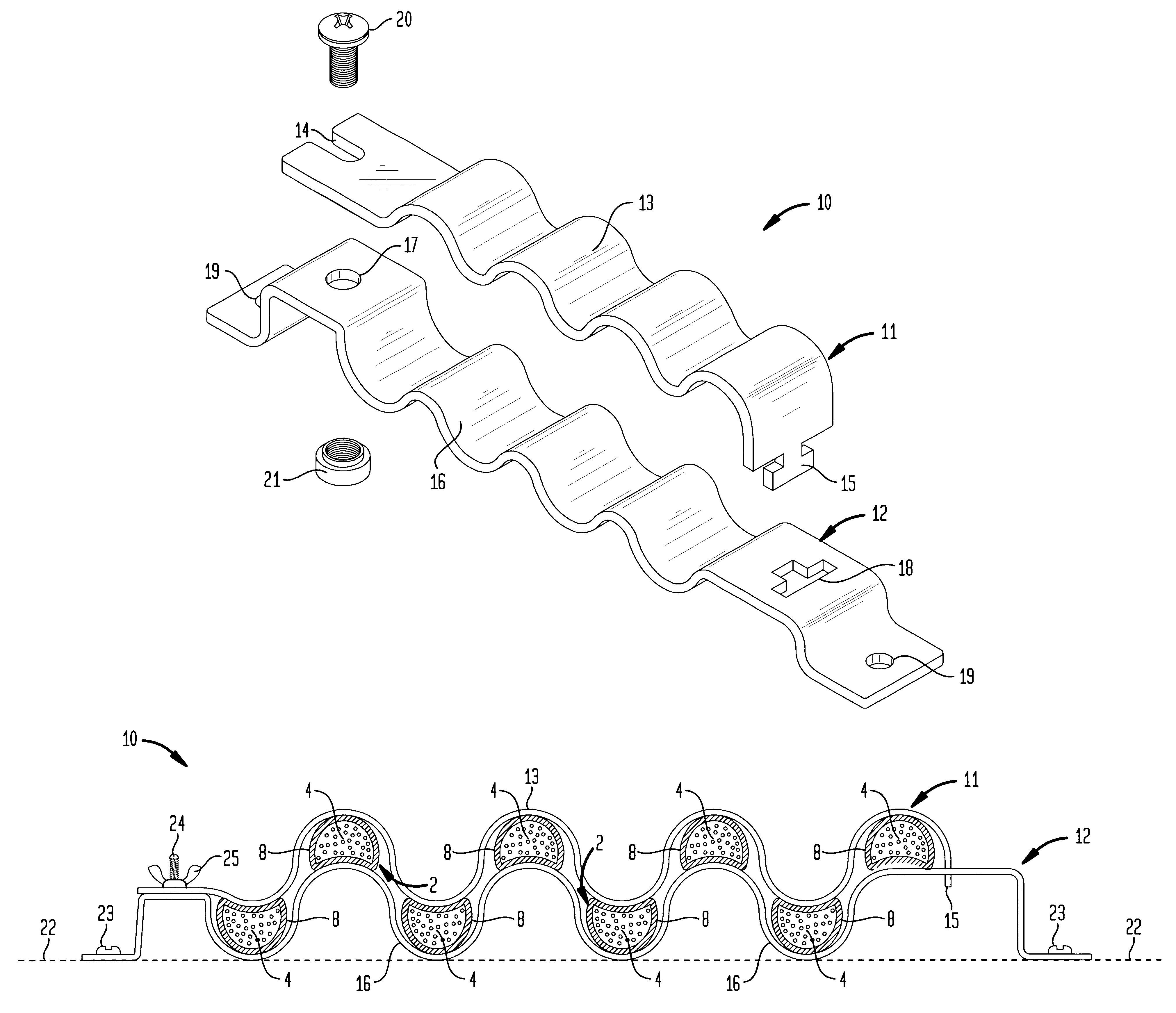
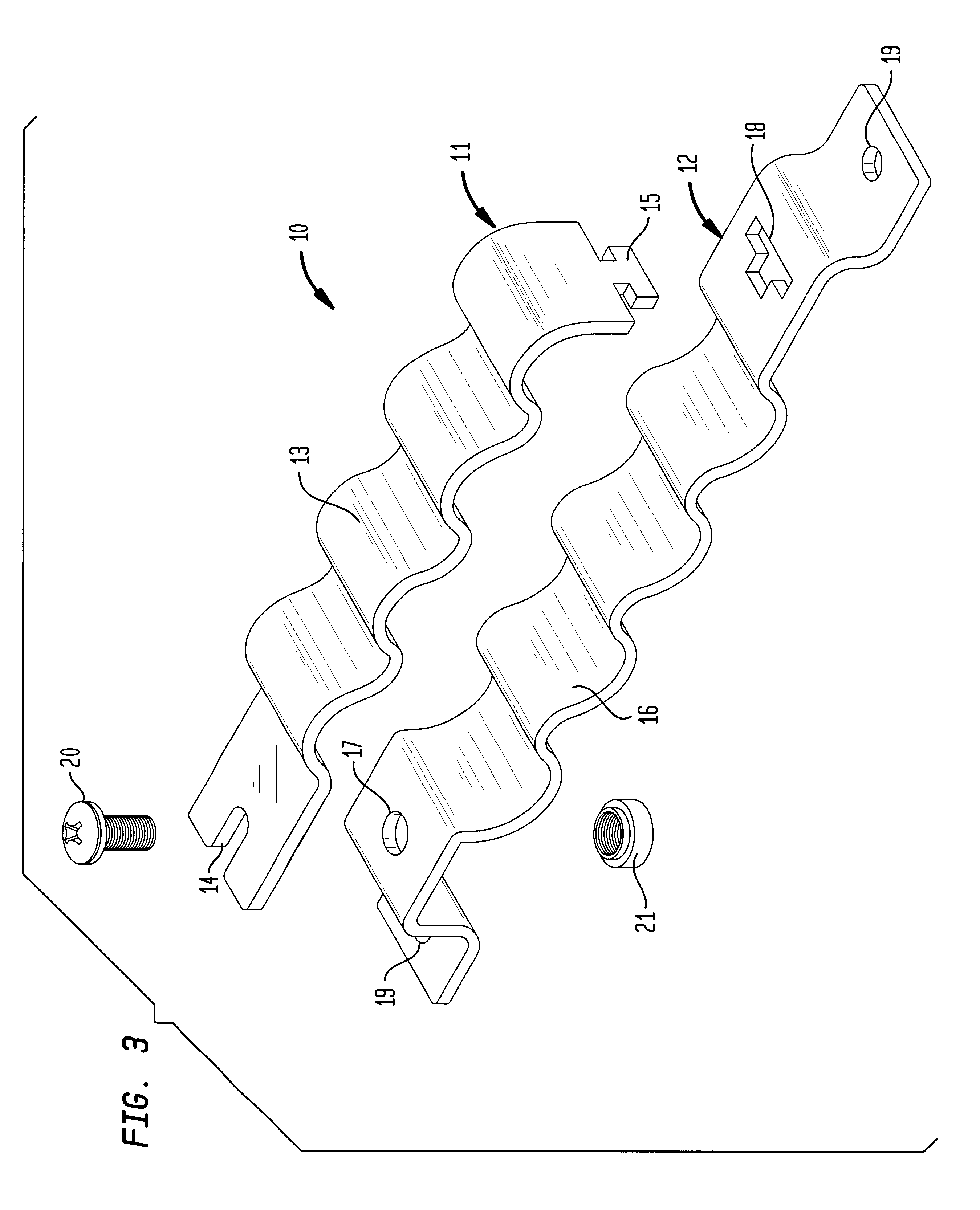
In FIG. 3, an improved grounding clamp 10, according to the present invention, includes a first bracket 11 and a second bracket 12 constructed of an electrically conductive material, such as a base metal or alloy. The first bracket 11 is characterized by a first undulating surface 13 having a plurality of sequential peaks and valleys. One end of the first bracket 11 includes a through channel 14, and the other end includes a downwardly oriented locking tab 15. The locking tab 15 is T-shaped.

The second bracket 12 is characterized by a second undulating surface 16 having a plurality of sequential peaks and valleys. One end of the second bracket 12 includes a through hole 17, and the other end includes a locking slot 18. The locking slot 18 is also T-shaped. Both ends of the second bracket 12 also include fastener openings 19.

The first bracket 11 may be loosely attached to the second bracket 12 by inserting the locking tab 15 into the locking slot 18, and slightly moving the first brac...


PUM


Abstract

A grounding clamp includes mechanical features for electrically interconnecting two or more shielding layers of shielded cables, and / or for interconnecting the shielding layer of one or more shielded cables to an electrically grounded chassis. The grounding clamp includes two elongated brackets, each having a first end and a second end, and each being formed of an electrically conductive material. The two brackets include undulating surfaces, and are interconnected to each other at their first ends by a tab and slot arrangement. When the two brackets face each other the undulations on their undulating surfaces are offset relative to one another. The second ends of the brackets are connected by a threaded fastener arrangement, so that cables may be pinched between the undulating surfaces to establish electrical conductivity between shielding layers of the cables and the grounding clamp. One of the two brackets may also include fastening features allowing the grounding clamp to be physically and electrically connected to a grounded chassis.

Description

1. Field of the InventionThe present invention relates to a clamp for holding one or more transmission cables.2. Description of the Background ArtFIGS. 1 and 2 illustrate a grounding clamp 1, in accordance with the background art. The grounding clamp 1 physically and electrically interacts with a plurality of shielded cables 2 and an electrically grounded chassis 3 of a piece of electrical equipment. The purpose of the grounding clamp 1 is to equate the ground levels of the shielded cables 2 to the ground level of the grounded chassis 3, in order to reduce the likelihood of electrical noise. The grounding clamp 1 also serves to provide strain relief to electrical connections made between the conductors 4, within the shielded cables 2, and terminals, within the electrical equipment. Further, the grounding clamp 1 acts to organize the shielded cables 2, so that the shielded cables 2 are directed in a set direction and are not free to move about.The physical and electrical interaction ...

Claims


Application Information

Patent Timeline
Patent Type & Authority Patents(United States)
IPC IPC(8): F16L3/22H01R4/64H05K9/00H01R13/648F16L3/223
CPCF16L3/223F16L3/2235H01R4/646H05K9/0018H01R13/648H02G3/26
Inventor CAMPOREALE, SAVINOFEINER, MARK E.MESSINA, SEBASTIAN J.RUSH, NANCY S.
Owner LUCENT TECH INC
Learn More