Wastewater flow control system

a flow control and sewage technology, applied in the direction of pump control, positive displacement liquid engine, fluid engine, etc., can solve the problems of affecting the operation of the pump

Inactive Publication Date: 2001-06-05
FLOW CONTROL SYST
View PDF5 Cites 47 Cited by
  • Summary
  • Abstract
  • Description
  • Claims
  • Application Information

AI Technical Summary

Problems solved by technology

Lift stations or pump stations are required because a point is reached where it becomes impractical to lay gravity-flow sewer lines any deeper underground.
Cavitation is a major problem that may occur in wastewater pumping systems.
This imploding action occurs violently and attacks the face of the impeller.
An impeller that has been operating under a suction cavitation condition has large chunks of material removed from its face causing premature failure of the pump.
A pump that has been operating under these conditions shows premature wear of the impeller vane tips and the pump cutwater.
In addition, due to the high-pressure condition, premature failure of the pump mechanical seal and bearings may occur and under extreme conditions will break the impeller shaft.
Another problem peculiar to wastewater collection systems is blockage of the system and components by the solids within the sewage.
Another problem peculiar to wastewater collection systems is the unpredictable flow rate of wastes through the system.
Both of these options increase the cost for components and maintenance and operation of a pump station.
Another problem peculiar to wastewater collection systems is the backpressure encountered from force mains.
Premature failure of the centrifugal pump due to damage from blockage or cavitation is undesirable.
Failure of the pump to operate, or failure to fulfill flow requirements can cause sewage back-up and overflow from the wet well with obvious undesirable consequences to the environment in the vicinity of the pump station.
However, since the electric motors to be powered by the engine-driven generator typically can require for startup up to 400 percent of the power needed for normal running, the engine-driven generator must be an oversized expensive machine which can cost a considerable amount of money.
Such equipment is infrequently used and, even then, seldom at full capacity.
This equipment can also be quite expensive.
These solutions also do not address the basic problems of clearance of blockages and cavitation that most often cause the premature failure of the pump.

Method used


Image

  • Wastewater flow control system
  • Wastewater flow control system
  • Wastewater flow control system

Examples


Embodiment Construction

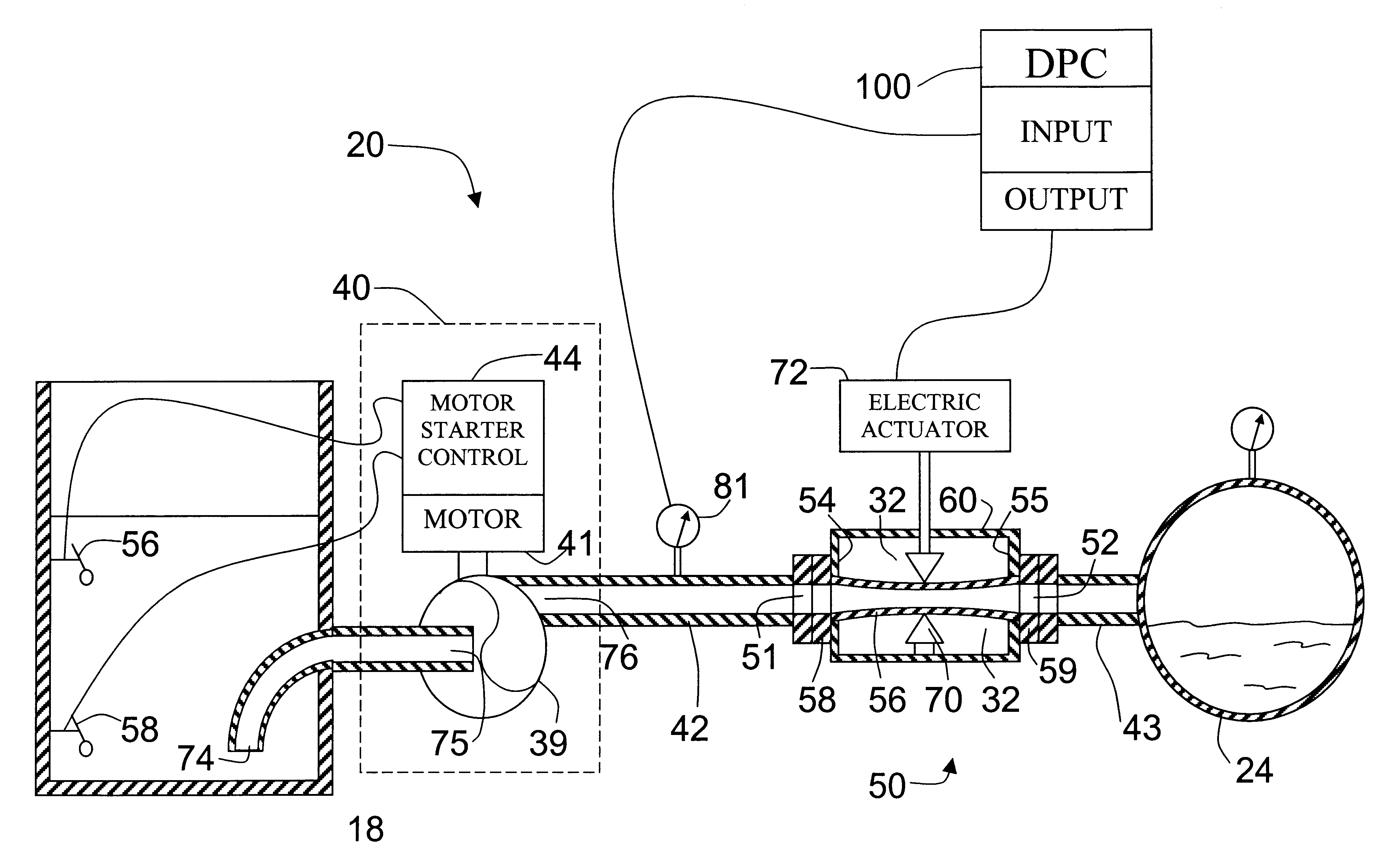
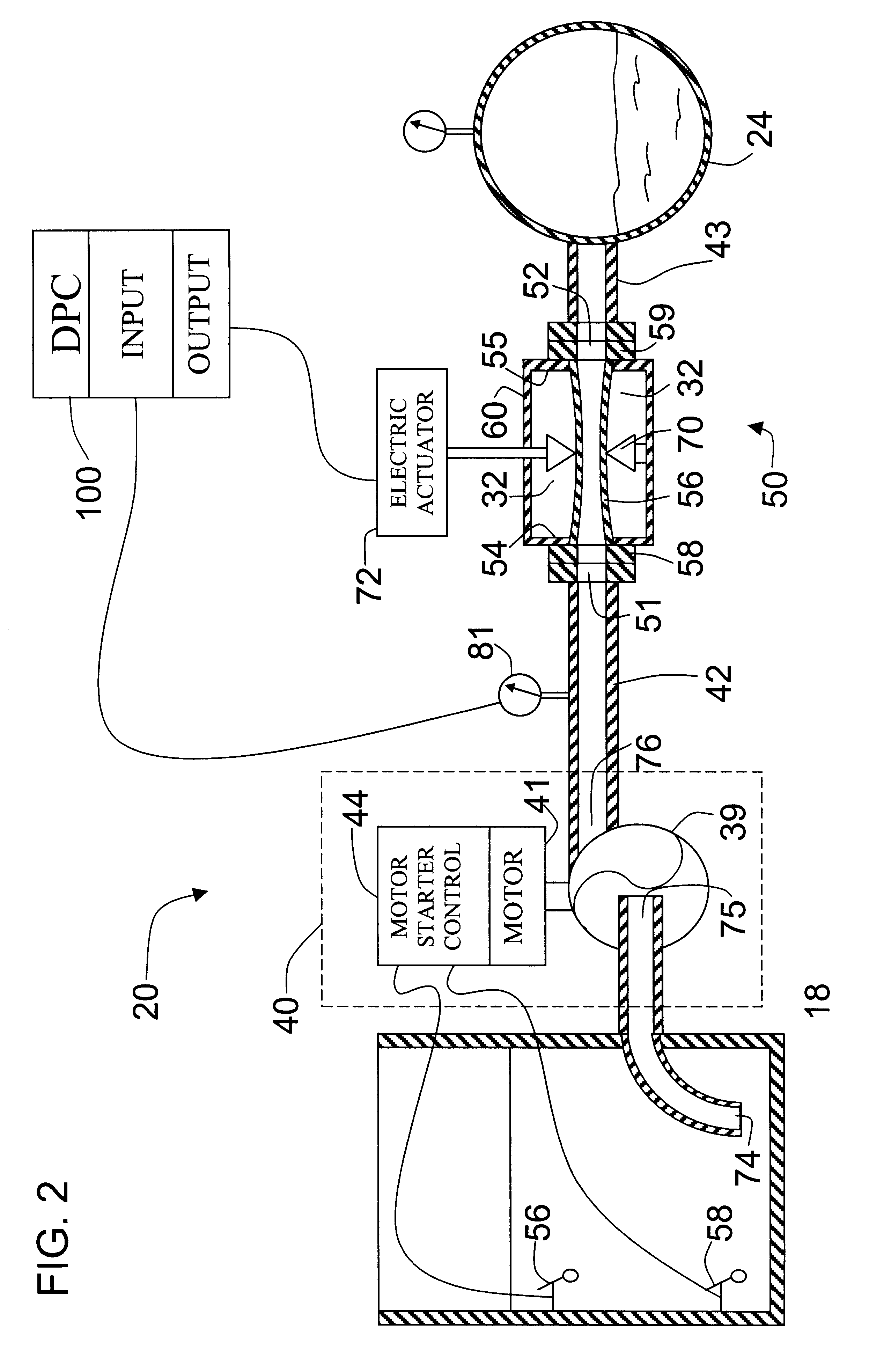
The present invention uses several different pieces of equipment in combination to control the pressure and or flow of a wastewater pump to prevent it from either overloading the motor or causing cavitation inside the pump, or from subjecting the pump to conditions outside its design parameters. Because of the problems unique to the treatment of raw sewage, including: clogging of control devices, and reliable pumping of raw sewage using any control means whatsoever, this type of control system has not heretofor been suggested in the art. The invention employs in combination several devices including a pinch valve, which has a flexible membrane designed to control the flow of a medium, including a waste stream containing solids such as raw sewage. The invention also uses a Digital Process Controller (DPC) in combination with a pressure or flow sensing device and the automated pinch valve. The control system is also self cleaning, due to the fact that when plugging occurs, the DPC in ...


PUM


Abstract

A sewage pumping apparatus is provided for delivering sewage collected by gravity in a wet well to a force main. The sewage pumping apparatus comprises a motor controlled pump in fluid communication with the wet well for supplying sewage to the force main via a pinch valve. A fluid parameter sensing device is provided at the outlet of the pump for producing an electrical signal output proportional to the sensed fluid parameter (pressure or flow rate). A Digital Process Controller (DPC) receives and compares the electrical signal from the fluid parameter sensing device to a system setpoint and produces a signal outputs to open or throttle the pinch valve in accordance with the desired system backpressure to prevent overloading or cavitation of the pump and to clear blockages in the system.

Description

1. Field of the InventionThis invention relates generally to sewage wastewater transport systems. More specifically, the present invention relates to a feedback control system downstream from a pump for delivering sewage from a wet well to a force main. In the present invention, the pump and a valving system respond to the pressure or flow sensed downstream of the pump to ensure the proper operation of the pump while delivering wastewater into the force main.2. Description of the Prior ArtWastewater and sewage are transported to a treatment plant via a collection system. The terms "sewage" and "wastewater" as used herein are defined as the liquid waste containing both dissolved and suspended solids resulting from the discharge of toilets, baths, sinks and other fixtures in residential building or commercial establishments. Sewage also includes other suspended solid items that enter the waste collection stream, for example through open sewer drains, including trash, wood, dead animal...

Claims


Application Information

Patent Timeline
Patent Type & Authority Patents(United States)
IPC IPC(8): F04D15/00
CPCF04D15/0022
Inventor WARWICK, JOHN W.
Owner FLOW CONTROL SYST
Why Eureka
Try Eureka