Edger blade sharpener

Inactive Publication Date: 2001-06-05
SKINNER RICHARD
View PDF3 Cites 4 Cited by
  • Summary
  • Abstract
  • Description
  • Claims
  • Application Information

AI Technical Summary

Problems solved by technology

However, absent in the art are any such devices particularly designed for the sharpening of the blades of powered lawn edging equipment.
One problem with these devices, however, is that the blade t

Method used


Image

  • Edger blade sharpener
  • Edger blade sharpener
  • Edger blade sharpener

Examples


Embodiment Construction

of the Figures

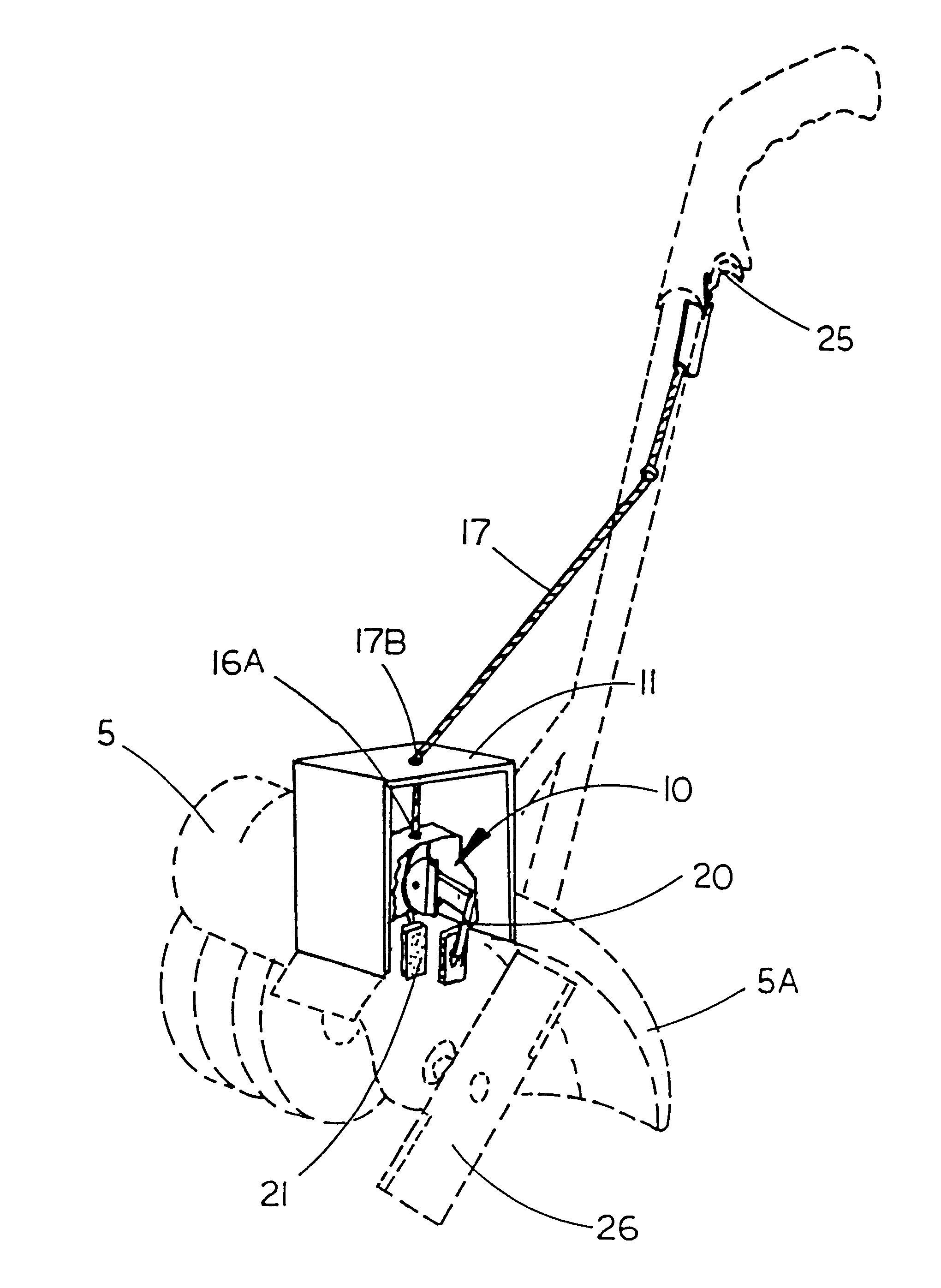
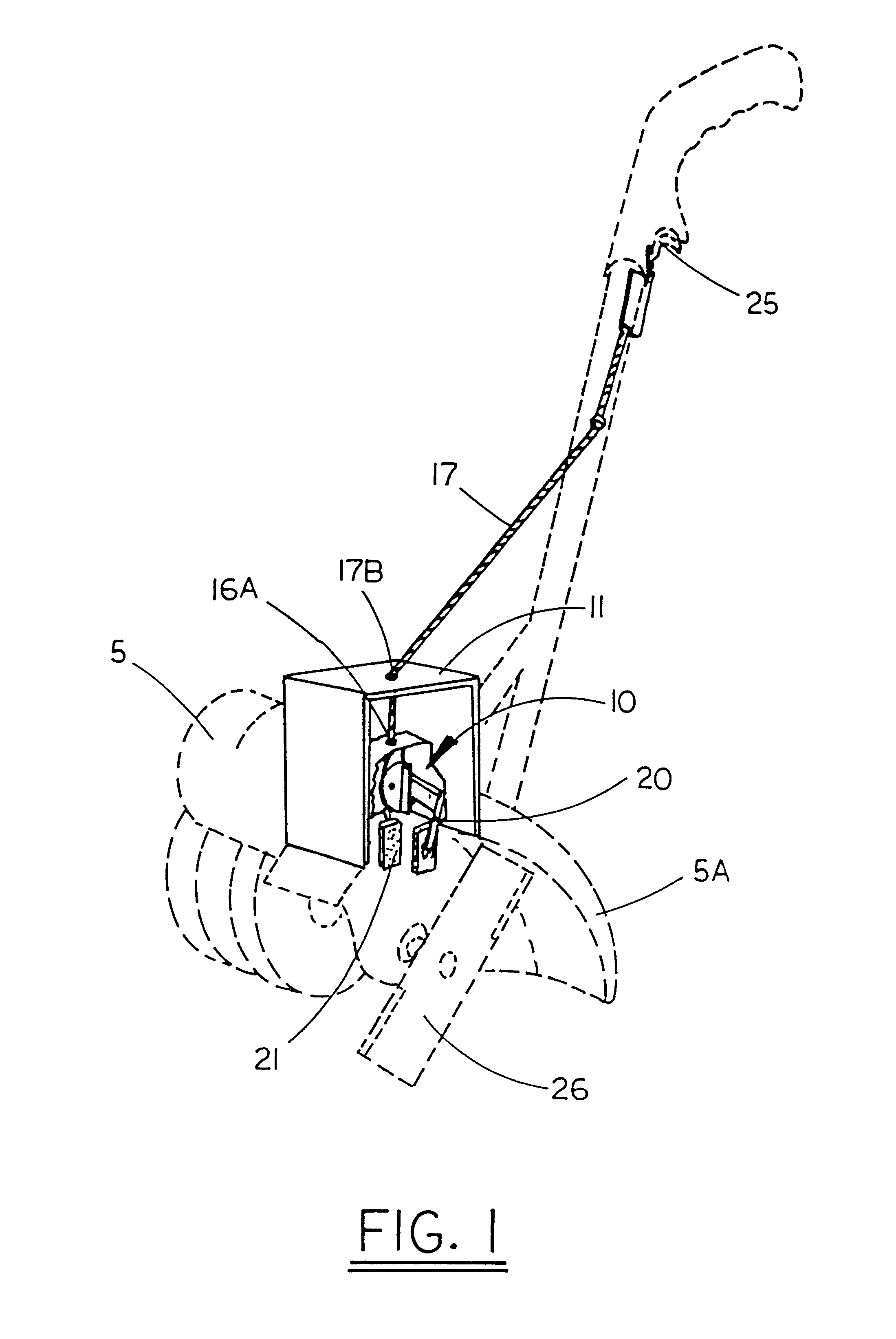
Referring to FIG. 1, a perspective view of a conventional powered rotary edger 5 (not part of the disclosure) is shown with an Edger Blade pener 10 installed. Edger 5 may be powered by either a gasoline or electric motor typically mounted on top of a housing containing a gear box with a sidewardly extending rotating shaft protruding therefrom. This is the shaft which rotates a blade in the vertical plane for trimming the turf along the edge of a sidewalk or driveway. Also typical is a wheel connected to the housing for rollably supporting edger 5 on the sidewalk or driveway.

A trigger 25 is connected to the handle of edger 5 via clamp 25a (not shown) and located within convenient reach of the user. Connected to trigger 25 is a cable 17 for transmitting the user's draft on trigger 25 to the operating mechanism of the Edger Blade Sharpener 10 via cable 17. Whenever the user desires to sharpen the rotating blade of edger 5, one need only pull trigger 25 for a short period ...


PUM

PropertyMeasurementUnit
Timeaaaaaaaaaa
Strengthaaaaaaaaaa

Abstract

This invention is a sharpening device for lawn edger blades. The device is specifically designed for attachment to the machine and in use for when the machine is in operation. The reason for this is to keep the cutting edge of the blade continually sharp. The attachment is positioned near the cutting edge and sharpens the blade as it rotates. A manual switch or lever activates the sharpener as the user desires. The sharpener includes a caliper with an abrasive surface to squeeze against the rotating blade while the edger is in operation.

Description

There are no previously filed, nor currently any co-pending applications, anywhere in the world.1. Field of the InventionThe present invention relates generally to blade sharpening devices and, more particularly, to a blade sharpening device for lawn edgers.2. Description of the Related ArtIn the prior art, devices for sharpening the blades of power equipment such as lawn mowers are well known. However, absent in the art are any such devices particularly designed for the sharpening of the blades of powered lawn edging equipment.Many Americans spend countless hours maintaining and beautifying their lawns and landscape. As a matter of pride and personal expression, these people manicure their grass, plant and maintain flowers, shrubs, bushes and trees all for the sake of enhancing the aesthetic qualities of their property. In performing these tasks one uses a variety of tools and machinery, each of which performs a specialized yard care or maintenance function. Among these devices, th...

Claims


Application Information

Patent Timeline
IPC IPC(8): B24B3/36B24B3/00B24B7/17B24B7/00
CPCB24B3/365B24B3/368B24B7/17
Inventor SKINNER, RICHARD
Owner SKINNER RICHARD
Why Eureka
Try Eureka