Shock absorber cushion for flexographic printing plate and method of use

Inactive Publication Date: 2001-06-19
RANDAZZO JEFFREY A
View PDF9 Cites 26 Cited by
  • Summary
  • Abstract
  • Description
  • Claims
  • Application Information

AI Technical Summary

Problems solved by technology

(1) Hard Tape--no significant or claimed cushioning affect. This tape is best used when large amounts of ink need to be applied at 100% strength (full strength). However, since this tape has no inherent ability to even out the mechanical tolerances of the printing press, more than minimal pressure is normally required. This pressure creates a distorted printed image appearing in various forms which may include hard edges around the outer portion of the line copy while leaving a halo adjacent to this hard edge. Depending upon impression required, text may be squeezed to a point where it begins to slur (elongated the print in a through-press direction).
(2) Soft Tape--used as a cushion to allow even impression across and around the cylinder. This is because soft foam tape collapses or compresses under pressure in the areas that come into impression first which represent the largest circumference of the print package and must be impressed several thousands more until the entire image appears to be printing evenly and uniformly. Because of its softness, this material is used primarily when fine details or extremely small images are printed to help minimize the distortion that occur

Method used


Image

  • Shock absorber cushion for flexographic printing plate and method of use
  • Shock absorber cushion for flexographic printing plate and method of use
  • Shock absorber cushion for flexographic printing plate and method of use

Examples


example

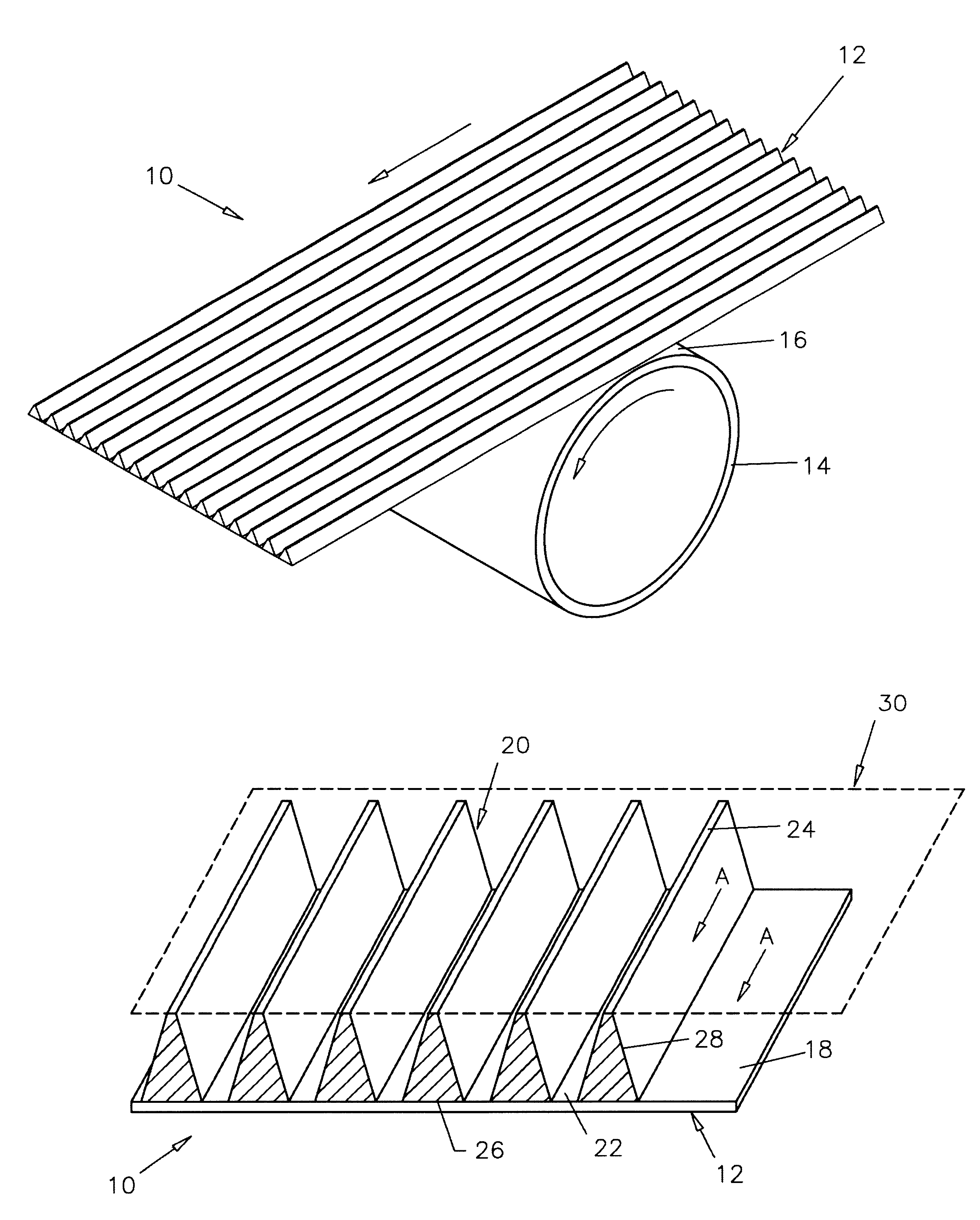
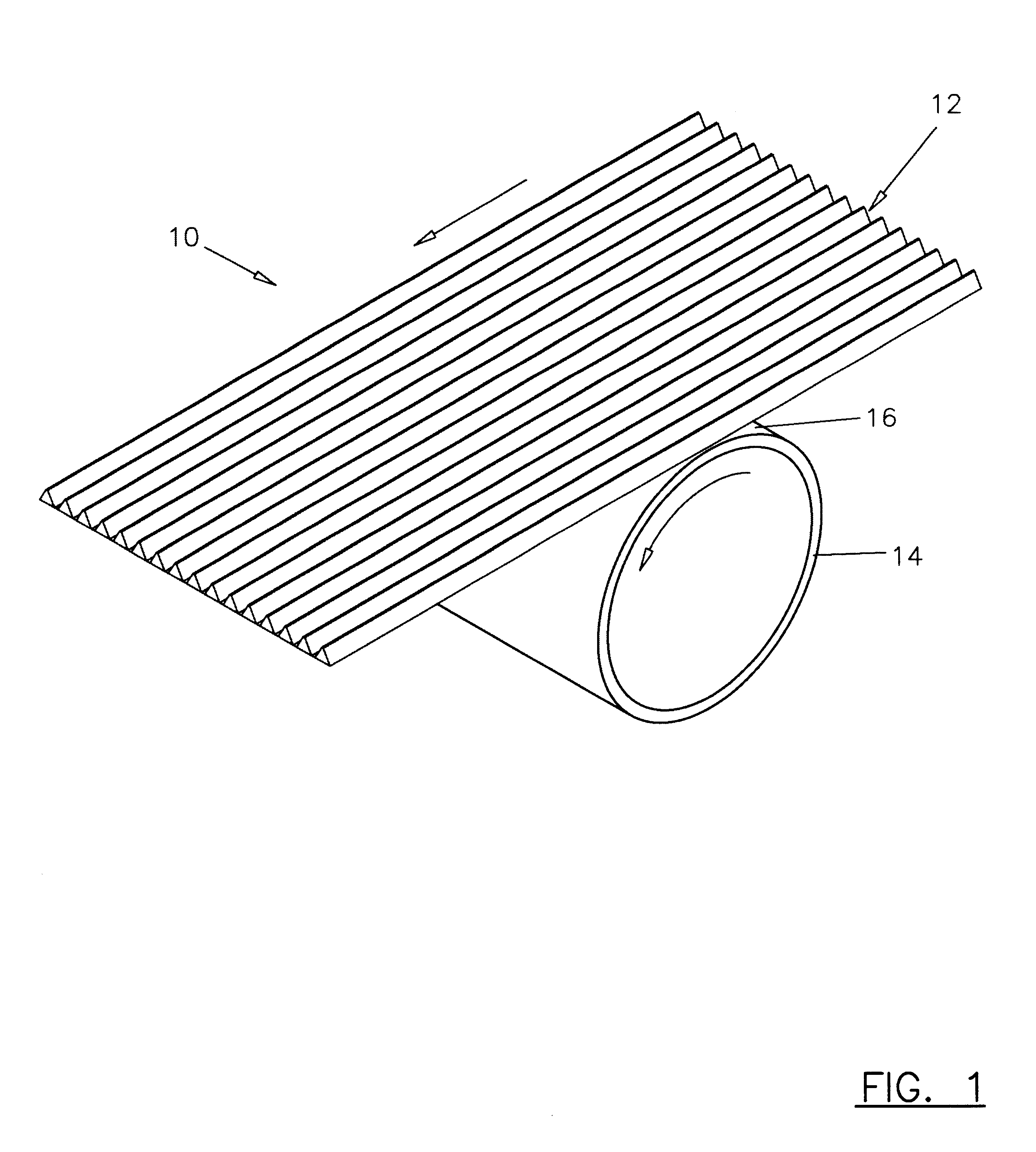
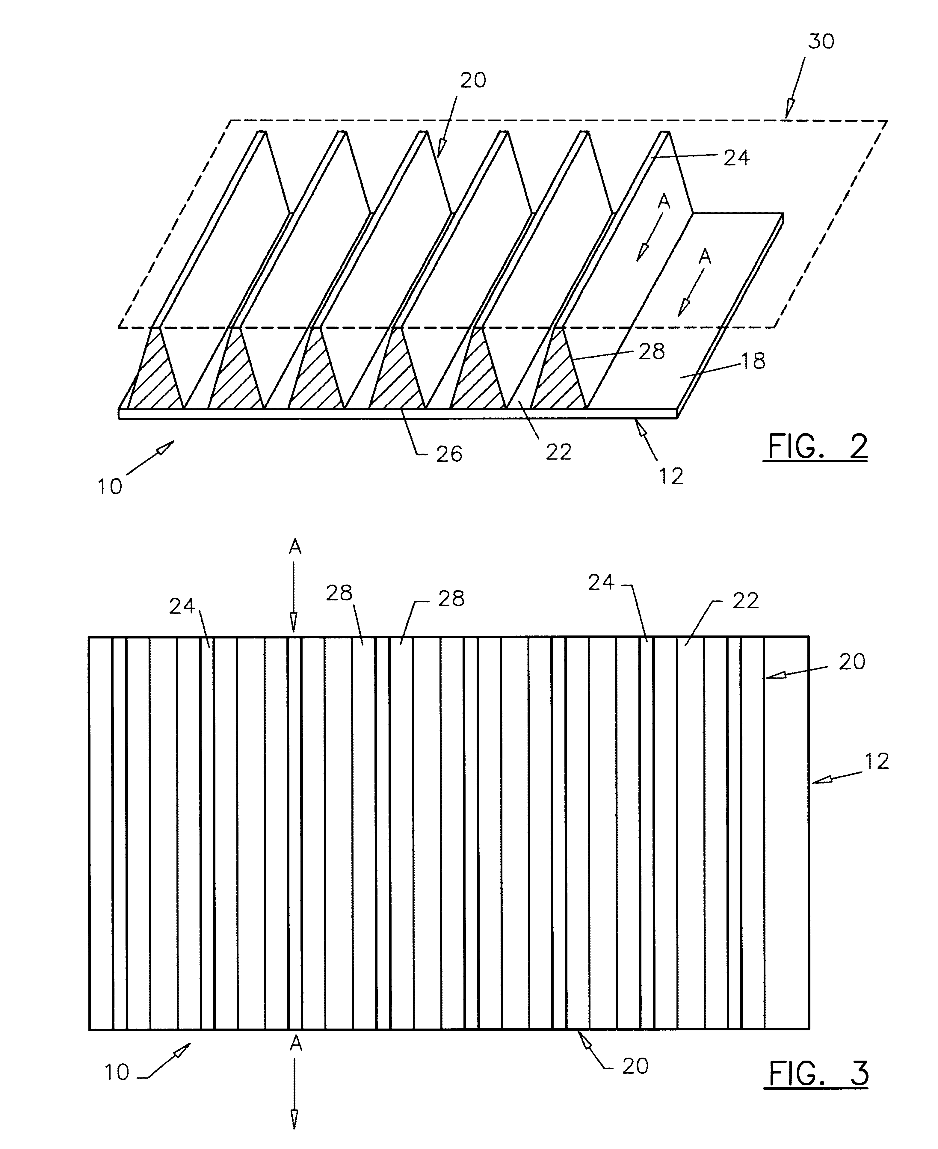
The characteristics in accordance with this invention were tested with displacement projections that were in straight line ranging in widths of 0.001 inches to approximately 0.3 inches. The second characteristic of the pattern used is the spacing between images. The present invention in experiment realized various levels that were successful when the void space was at least equal to the materials' surface image with spaces as great as ten times the image width. In accordance with this example, the most preferable image top width was 0.004 inches while maintaining a space between images of 0.042 inches. This creates an image support that, at its most narrow point, was 0.004 inches in expanding in width from the top of the blanket to the mylar base approximately 0.021 inches.

It is important that regardless of the geometrical cross-sectional shape that the protrusion element run essentially circumferentially, preferably without a break in the circumferential direction around the print ...


PUM


Abstract

A sheet of elastomeric material that serves as a shock absorber and cushion for use between a flexographic printing plate and a printing cylinder during printing for compensating for variations in thickness, height and centricity of the printing cylinder and flexographic printing plate to prevent distortions in the image being printed that includes providing an elastomeric sheet having a longitudinal direction in the direction of circumferential travel of the cylinder circumference that includes a plurality or array of protrusions formed of the elastomeric material of predetermined cross-sectional shape and area and the material having a durometer to cushion the flexographic plate in such a way to provide the necessary compensation to ensure a high quality printed image at high speed. The cross-sectional shapes and the array of the longitudinal protrusions provide for material displacement zones that allows the elastomeric material to be compressed and return relatively instantaneously to its original height or near original height in sharing high quality printing compensating for tolerance errors between the drum size and the flexographic plate thicknesses.

Description

1. Field of the InventionThis invention relates to a shock absorber and cushion for use between a flexographic printing plate and a printing cylinder during printing that compensates for variations in thickness, height and centricity of the materials and equipment used for printing to enhance the image quality and efficiency of the flexographic printing process without increasing printing pressure.2. Description of Prior ArtFlexography is a printing process used primarily in the packaging and newspaper industries. The flexographic process requires that a raised surface plate be used to transfer ink onto a given substrate. This is unlike lithography, which works on a flat plane based on the principle that oil and water do not mix. The gravure printing process is a recess process in which cells are engraved into the print cylinder that are then filled with ink and then transferred to the substrate.The flexographic printing process' unique capabilities include changing cylinder dimensi...

Claims


Application Information

Patent Timeline
IPC IPC(8): B41M1/00B41M1/04B41F13/08B41N6/00B41F27/00B41F27/14B41M9/00B41M9/04
CPCB41F13/085B41F27/14B41N6/00B41M1/04
Inventor RANDAZZO, JEFFREY A.
Owner RANDAZZO JEFFREY A
Why Eureka
Try Eureka