Moving apparatus with drive power assisting device and movement controlling method

a technology of assisting device and moving apparatus, which is applied in the direction of gas pressure propulsion mounting, association for rectification, propulsion parts, etc., can solve the problems of difficult assembly of crank shaft or chain, and difficulty in carrying out traveling only by human power

Inactive Publication Date: 2001-06-19
SONY CORP
View PDF32 Cites 149 Cited by
  • Summary
  • Abstract
  • Description
  • Claims
  • Application Information

AI Technical Summary

Benefits of technology

An object of this invention is to provide a novel moving apparatus and a movement control method for such a moving apparatus which can eliminate or solve the problems of the conventionally proposed bicycles with driving force assist mechanism.
In addition, in the moving apparatus according to this invention, in the case where the state of the road surface on which this moving apparatus moves has a necessity of assisting a portion of driving force for moving the moving apparatus, the electric motor is caused to be driven. On the other hand, in the case where the state of the road surface on which the moving apparatus moves has no necessity of assistant driving force for moving the moving apparatus, the electric motor is caused to function as a generator, thereby making it possible to reduce the power consumption of the secondary battery. This permits the moving apparatus to travel long distance.

Problems solved by technology

In such cases that bicycle adapted for carrying out traveling only by human power as mentioned above comes to the ascending slope (rising hill), it would become difficult to carry out traveling only by human power.
Meanwhile, since torque sensors used in the conventionally proposed bicycles with the driving force assist mechanism are torque sensors using the mechanical elements, the configuration thereof is complicated and they are difficult to be assembled into the crank shaft or chain, or the main shaft of the drive wheel.
Moreover, since such torque sensors using the mechanical elements are large-sized and are heavy in weight, a portion of the step-on force of the driver is consumed and a portion of the driving force (power) of the electric motor is consumed.
For this reason, the traveling efficiency is not good.
In addition, the torque sensors using the mechanical elements have delay in detection of the rotation torque.
As a result, it is difficult to quickly detect leg-power (step-on force) of the driver in dependency upon the traveling state to quickly drive the driving force assist unit in dependency upon the traveling state.

Method used


Image

  • Moving apparatus with drive power assisting device and movement controlling method
  • Moving apparatus with drive power assisting device and movement controlling method
  • Moving apparatus with drive power assisting device and movement controlling method

Examples


Embodiment Construction

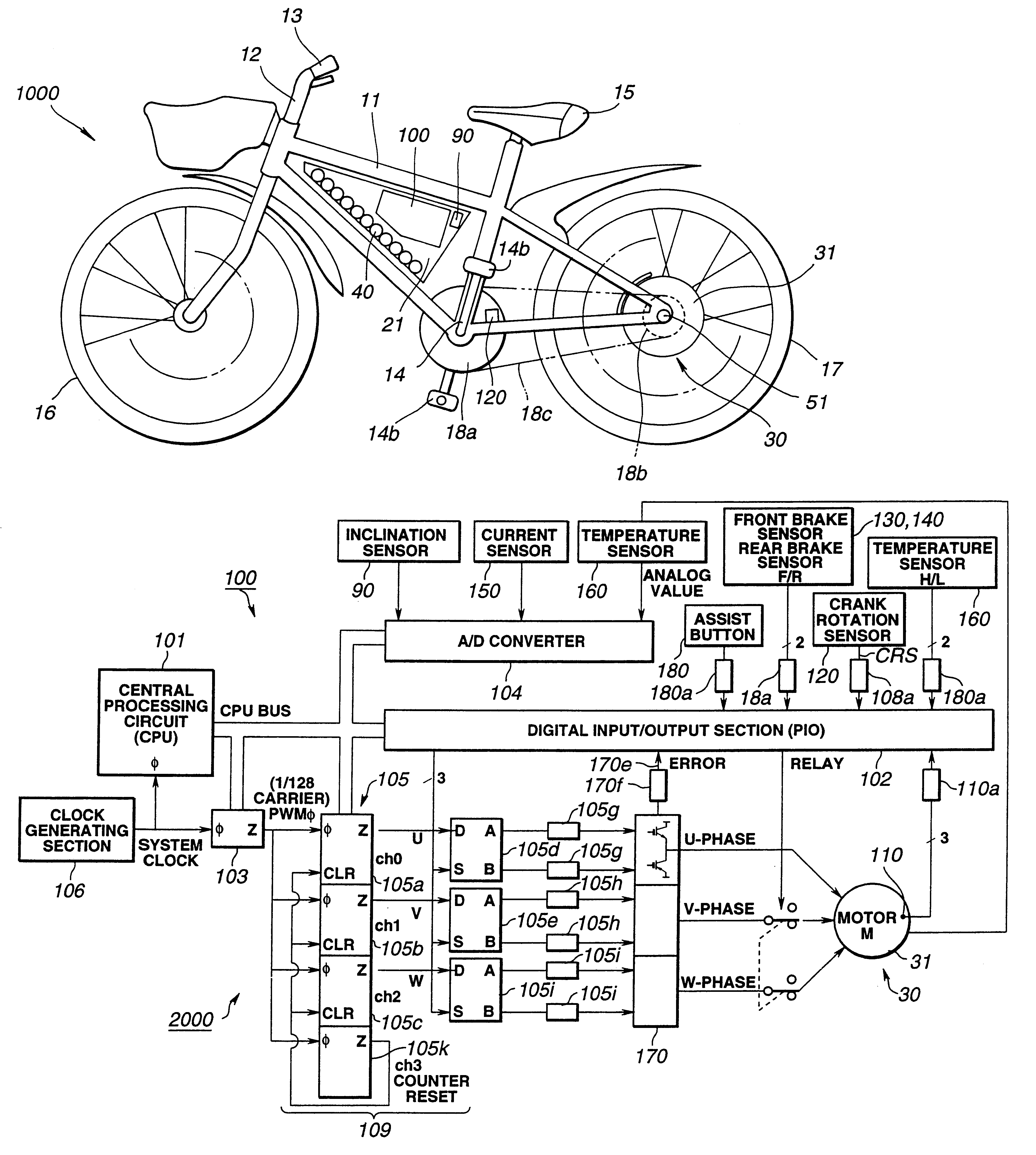
This invention will be described below by taking the example applied to, as a moving apparatus, a motor-operated bicycle moved by human power in an ordinary traveling state and moved in a state where the driving force of an electric motor formed of a drive force assist mechanism which is added as need arises.

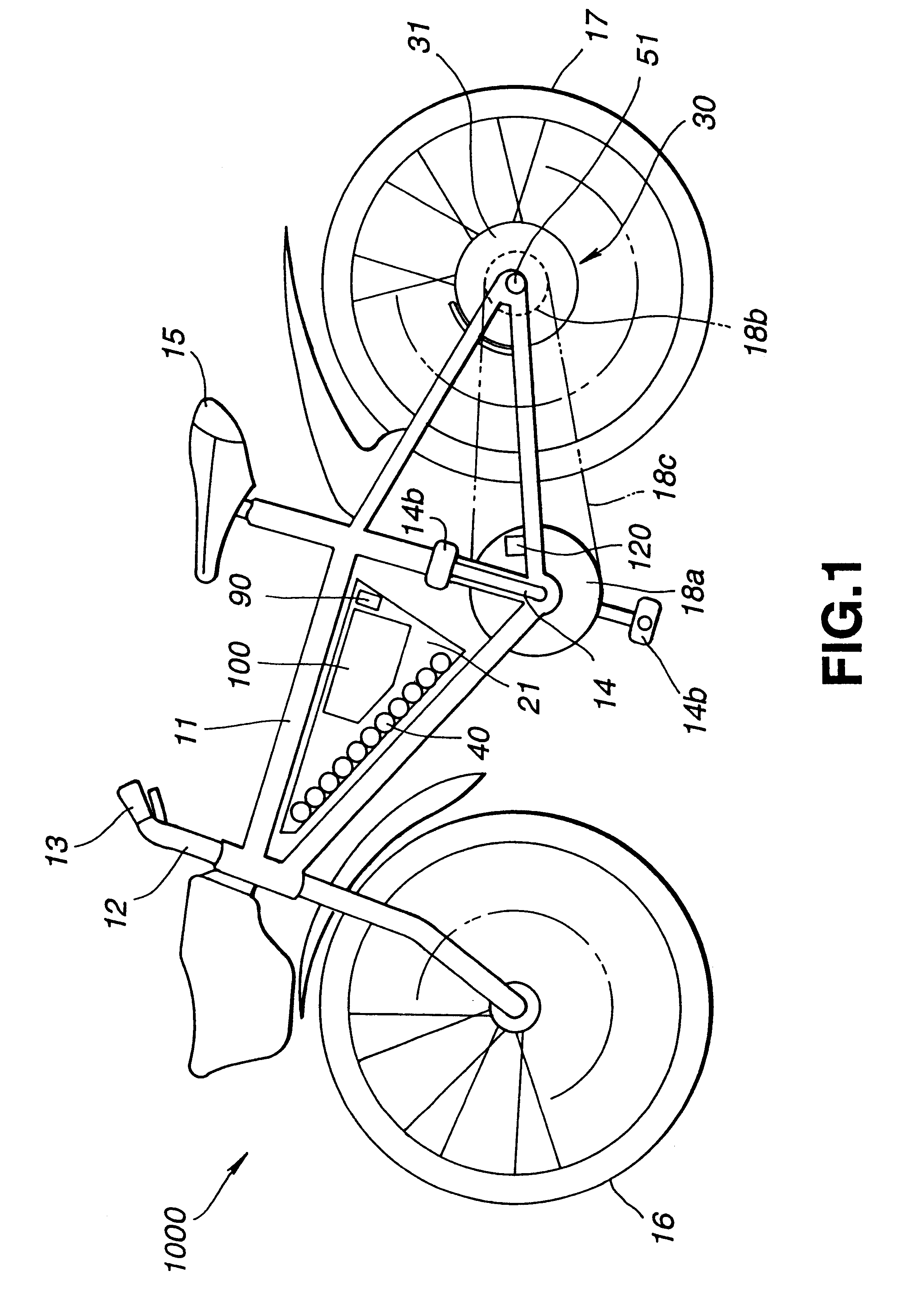
A motor-operated bicycle according to this invention comprises, similarly to the well known bicycle, a frame 11 which is generally of a triangular shape, a handle 12 for controlling traveling direction, grip portions 13 for operating the handle 12, a crank 14 which is rotated by the driver, a saddle 15 on which the driver sits, a front wheel 16 changed in a traveling direction by operation of the handle 12, a rear wheel 17 serving as a drive wheel rotated by undergoing rotational force of the crank 14, a first gear 18a rotating in one body with the crank 14, a second gear 18b rotating in one body with the rear wheel, and a chain 18c wound between first and second gears 18a, 18b,...


PUM


Abstract

A moving apparatus with a driving force assist mechanism traveled mainly by human power. This moving apparatus detects, in a non-contact manner, with respect to rotating portion such as traveling wheel, etc., rotation speed of the rotating portion to detect traveling state to deliver, from the driving force assist mechanism, assistant driving force corresponding to speed change information that a person who operates the moving apparatus intends to give on the basis of the detected traveling information to carry out traveling to thereby permit smooth traveling even in the case where traveling by only human power becomes difficult.

Description

This invention relates to a moving apparatus provided with a drive wheel driven by human power (strength) and a movement control method for such a moving apparatus, and more particularly to a moving apparatus provided with a driving force assist device using chargeable secondary battery as the drive source and adapted to carry out traveling by making use of the drive force from the drive force assist device in addition to human power in dependency upon the traveling state, and a movement control method for such a moving apparatus.Hitherto, as a moving apparatus adapted so that the drive wheel is driven by human power to carry out traveling, bicycles are widely used.In a bicycle, a person who operates the bicycle rides on the saddle to rotate the crank through the pedals by leg-power of the driver (operator) or force applied onto the pedal by the driver (hereinafter referred to as step-on force as occasion may demand) to transmit, to the drive wheel, rotation of the crank through the...

Claims


Application Information

Patent Timeline
Patent Type & Authority Patents(United States)
IPC IPC(8): B60L11/18B62M23/02H02J7/14H02K29/06H02K7/14H02K29/10H02K21/22H02K11/04G01R31/36B62M6/45B62M6/50B62M6/60
CPCB60L11/1801B60L11/007B62M6/45B62M6/50B62M6/65H02J7/1415H02K7/14H02K11/048H02K21/22H02K29/10B60L11/1872B60L2200/12B60L2240/36G01R31/36Y02T10/641Y02T10/7005Y02T10/705B60L50/53B60L50/20B60L58/25Y10T428/249923Y02T10/64Y02T10/70H02M7/00
Inventor HAYASHI, TOSHIRONANAE, YUICHIHAYASHI, HIROYOSHIKATAGIRI, ICHIROSATO, NAOMASAENDO, TETSUOITOH, HIROYUKI
Owner SONY CORP
Why Eureka
Try Eureka