In addition, other issues confronting the designer of a hard disk drive might include head positioning and data-
block transfer.
Typically, if the
servo-information is recorded at the same data-rate and within a positional relationship with the data-blocks, as has been conventionally employed, the servo-architecture is normally complex enough, in the sense of having information, to successfully switch data-rates and servo positions.
However, if regularly spaced servo-information were radially placed across data-storage surfaces, while splitting some of the data-fields on those surfaces into segments, when data-zones are crossed-over complications could arise when trying to read each "Split Data-Field" as a single data-block.
Some hard disk drives do not use or normally include the complication of zoned-
data recording and Split Data-Fields.
In other words, the "average
access time" ratings of conventional Flying-Head hard disk drives can be seriously outmatched by the Microhead Array Chip design.
This is because 60% of flying-head hard disk drive failures are caused by rotary-voice-coil mechanical malfunctions or because of flying-head hard disk crashes.
In fact, within a rotary positioner Flying-Head design, Flying-Head distances of "1.0" to "2.5" microns would be difficult to maintain, if not impossible, were it not for the previously mentioned
air bearing and the aerodynamic design of head-sliders.
Furthermore, hard disk drive failure often occurs when the head-stack assembly has not been properly positioned into the hard disk drive's innermost disk-platter area (i.e., sometimes called the head
parking area).
When the Spindle-Motor's power fails and the hard disk drive
spins-down the
air bearing which keeps the head-sliders aloft and flying will begin to decrease and decay.
Consequently, with the loss of this
air bearing the head-sliders can no longer maintain lift, and will ultimately
crash (i.e., come in contact with) into the hard disk drive's data-platter data-surfaces.
This is sometimes called "hard disk crashing" and accounts for about 60% of all hard disk drive failures.
There can be many root-causes leading to this kind of hard disk drive failure like
EEPROM-
BIOS failure, Disk-Controller failure, and Spindle-Motor failure.
However, whatever the cause, the end-result is always the same, hard disk crashes and severe data-loss.
Whether a Microhead Array Chip Hard Disk Drive's Spindle-Motor fails causing the drive to power down or there is some kind of
system (
BIOS) "Basic-In-Out-
System" failure.
However, an increase in Induction Channel Coil windings has an inherent design-flaw, which occurs in all
induction coil magnetic-head designs, and that flaw is called "
reactance".
However, this will also decrease a microhead's ability to respond to the fast current-reversals that are necessary in a "near field"
induction coil head design.
Moreover, "
reactance distortion" is why conventional high-frequency Flying Heads can use no more than five
induction coil winding tum's per Flying-Head Yoke Core, and why Flying Head head-sliders are now being flown above hard disk drive data-surfaces at distances of "1.0" micron or less.
Nevertheless, "
reactance distortion" will still occur within these high-tum Induction Channel Coils.
(i) Because, the problem of reactance
distortion will adversely effect the frequency-response of the microhead's Induction Channel Coils only during a write-data disk operation.
Therefore, Rotate-Toggling of a selected microhead's Alpha and Beta Induction Channel Coils during a read-data disk operation is unnecessary,
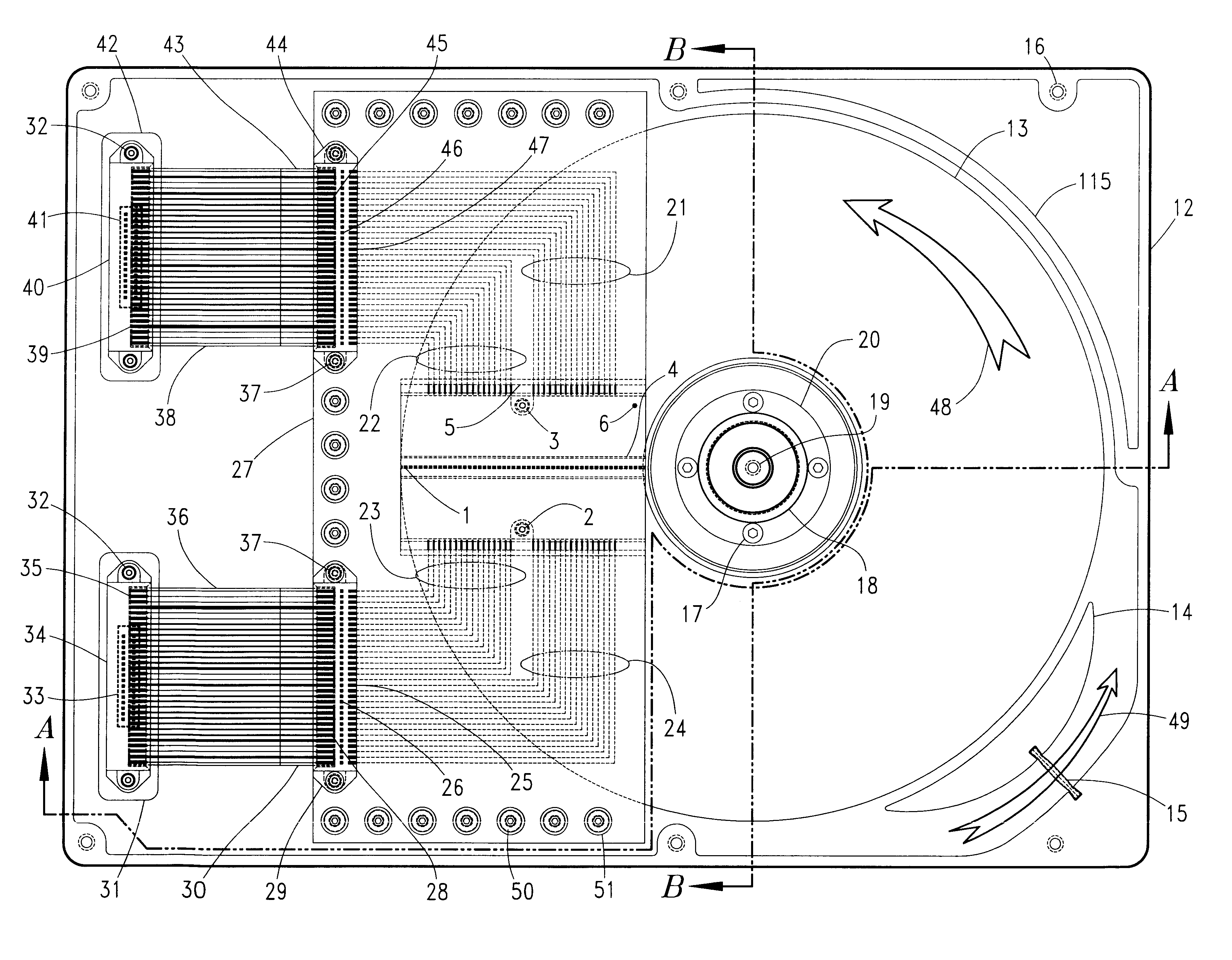
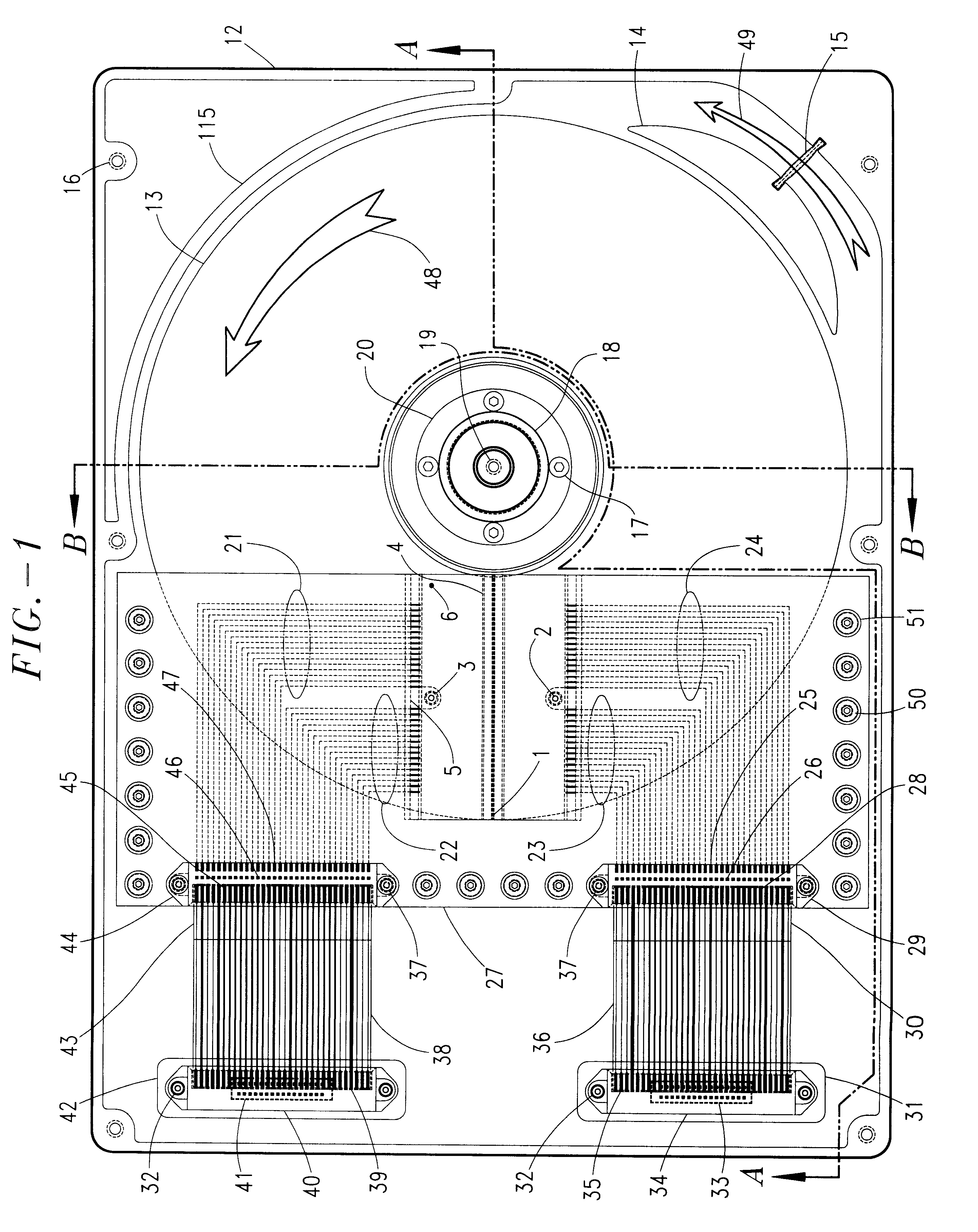
These
chip-positioning circuit boards are designed to be very rigid, non-flexible, and lightweight.
Furthermore, data-transfer rates determined by "
data rate preamble sync mark" read processes can be affected by any Spindle-Motor fluctuations and rotational speed-variances, causing data-transfer read-errors.

