Air bag gas inflator

a gas generator and air bag technology, applied in the direction of pedestrian/occupant safety arrangement, vehicle components, weapons, etc., can solve the problems of air bag inflation applying a sudden and large impact to a small child, increasing the inflating rate of air bags, and air bags being inflated by an excessive internal pressur

Inactive Publication Date: 2001-07-03
DAICEL CHEM IND LTD
View PDF7 Cites 73 Cited by
  • Summary
  • Abstract
  • Description
  • Claims
  • Application Information

AI Technical Summary

Problems solved by technology

The rapid inflation of the air bag may apply a sudden and large impact to a small child when he or she is not in a regular seating posture.
Moreover, when the degree of an impact is large, two ignite

Method used


Image

  • Air bag gas inflator
  • Air bag gas inflator

Examples


Embodiment Construction

Now, a description will be given in more detail of an embodiment of the present invention.

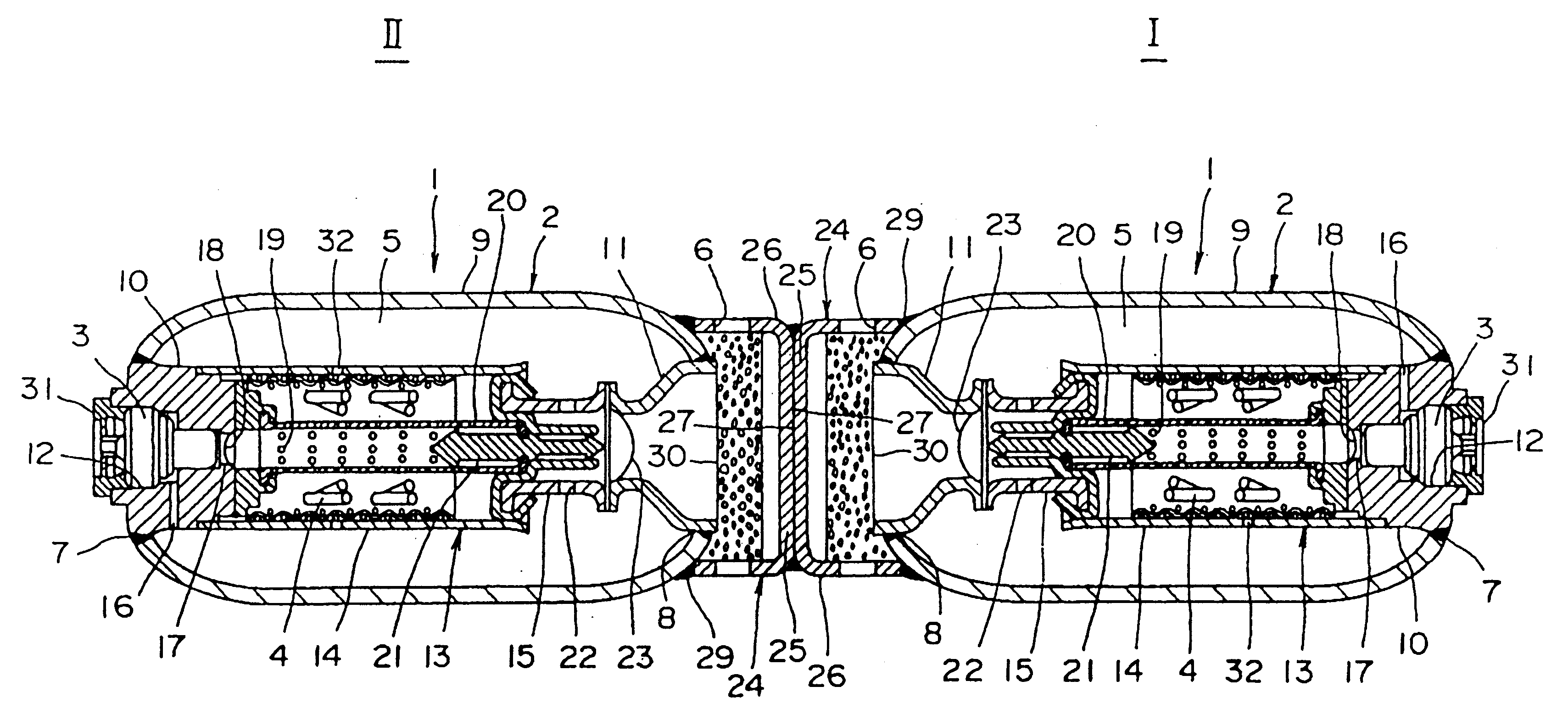
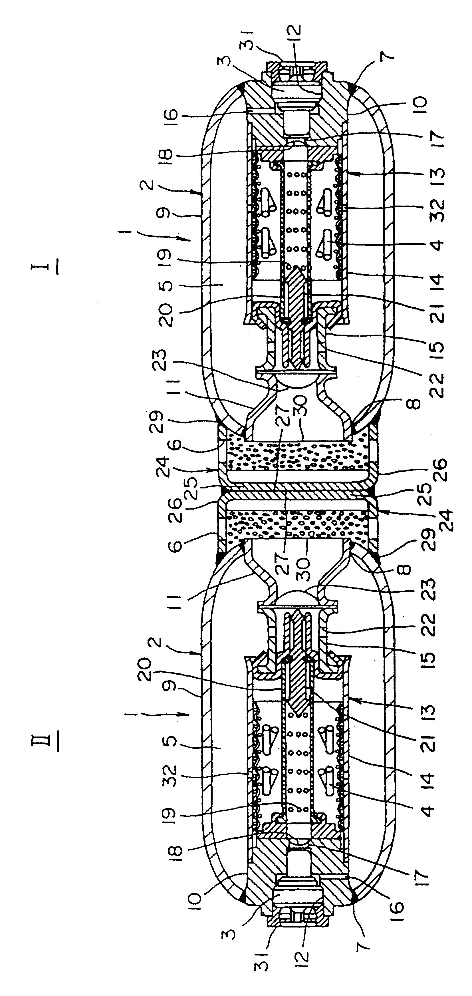
FIG. 1 is a cross-sectional view showing a gas generator for an air bag in accordance with an embodiment of the present invention. The gas generator includes two gas generating units 1 connected to each other in an axial direction. These two gas generating units 1 are of the same structure. Each of these two gas generating units 1 includes a cylindrical housing 2, an ignition unit disposed at one end of the housing 2, that is, an electronic igniter 3, a gas generating agent 4, which is ignited by the igniter 3 to generate combustion gas, a pressurized gas 5 sealed in the housing 2 to generate a mixture gas with the combustion gas of the gas generating agent, and a gas exhaust outlet 6, which is disposed in the other end of the housing 2, for injecting the mixture gas.

The housing 2 includes a cylindrical body 9 having openings 7 and 8 on both ends thereof. An assembly 13 is disposed within the b...


PUM


Abstract

A gas generator for an air bag that can change deployment pattern of the air bag is provided. The gas generator includes two gas generating units connected in the axial direction, each of the gas generating units including a cylindrical housing, an igniter disposed in the cylindrical housing and operates upon receiving an operation signal, a gas generating agent ignited by the igniter to generate a combustion gas, a pressurized gas sealed within the housing and heated by the combustion gas of the gas generating agent to generate a mixture gas together with the combustion gas, and a gas exhaust outlet disposed at one side end of the housing and from which the mixture gas within the housing is injected. The two gas generating units are joined by welding one end of each of the housings of the gas generating units together.

Description

Field of the InventionThe present invention relates to a gas generator for an air bag that protects a driver or a passenger from an impact, and more particularly to a hybrid-type gas generator that seals pressurized gas therein.DESCRIPTION OF THE PRIOR ARTFor the purpose of protecting a driver or a passenger from an impact of a vehicle collision, a vehicle is equipped with an air bag device. The air bag device includes a sensor, a control unit, gas generator, an air bag, etc. The gas generator includes an igniter and gas generating means. In the hybrid-type gas generator, the gas generating means includes a gas generating agent and a pressurized gas.Upon detection of an impact by the sensor, a detection signal is supplied to the control unit, which conducts arithmetic operation in response to the detection signal. The control unit generates an output signal representative of the result of the arithmetic operation to the igniter. The igniter is thus operated. With this operation, the...

Claims


Application Information

Patent Timeline
IPC IPC(8): B60R21/26B60R21/263B60R21/272
CPCB60R21/272B60R2021/2633B60R2021/26058
Inventor FUKABORI, MITSUHIKO
Owner DAICEL CHEM IND LTD
Why Eureka
Try Eureka