Calibrating write pre-equalization in a data storage device

a data storage device and write preequalization technology, applied in the field of data storage device calibration write preequalization, can solve the problems of high data bit-rate, high non-linearity of write drivers in digital magnetic data stored systems, and inefficient writing of data to magnetic media using ferrite heads

Inactive Publication Date: 2001-07-03
HEWLETT-PACKARD ENTERPRISE DEV LP
View PDF9 Cites 13 Cited by
  • Summary
  • Abstract
  • Description
  • Claims
  • Application Information

AI Technical Summary

Problems solved by technology

However, writing data to magnetic media using ferrite heads becomes more inefficient at high data bit-rates.
At high frequencies the losses due to irreversible heating of the write head results in a roll-off of the output of the write head for a given input current.
However, write drivers in digital magnetic data stored systems are highly non-linear devices.
Hence, any prior art attempts to boost high frequencies in such devices have been complex.
However, the Ampex implementation of write pre-equalization required substantial power, typically of the order 15 Watts, and could only be produced using discrete components.
Hence it is not possible to implement this as a single application specific integrated circuit (ASIC).
In addition, the Ampex scheme was also difficult to set up.
The effect of these non-linear lateral displacements of regions of magnetization on magnetic recording media can result in timing errors during a subsequent read operation of data stored on the storage medium and may result in an increase in the number of errors occurring during the read operation.
In such a method and apparatus, there exists a problem of optimizing the compensation means to minimise the number of errors occurring whilst reading data during a send operation.

Method used


Image

  • Calibrating write pre-equalization in a data storage device
  • Calibrating write pre-equalization in a data storage device
  • Calibrating write pre-equalization in a data storage device

Examples


Embodiment Construction

There will now be described by way of example the best mode contemplated by the inventors for carrying out the invention. In the following description numerous specific details are set forth in order to provide a thorough understanding of the present invention. It will be apparent however, to one skilled in the art, that the present invention may be practiced without limitation to these specific details. In other instances, well known methods and structures have not been described in detail so as not to unnecessarily obscure the present invention.

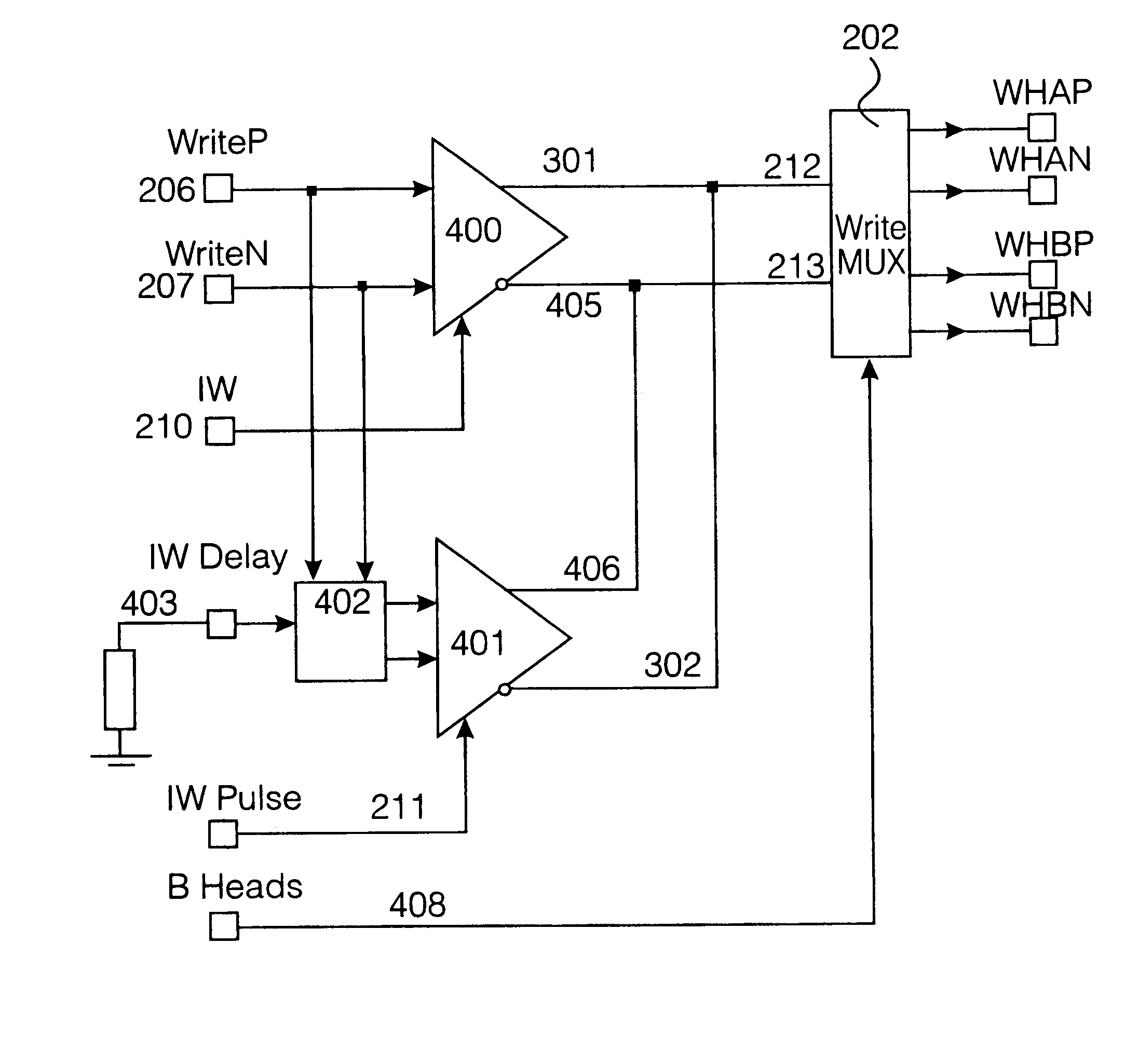
Specific methods according to the present invention described herein may be particularly suited to magnetic tape recording devices having a rotating read / write head in which an elongate tape is drawn past the head and the read / write heads rotate about an axis aligned at an angle to the direction of the tape motion. However, the generality of the present invention described herein is limited in scope only by the essential features according ...


PUM

PropertyMeasurementUnit
frequencyaaaaaaaaaa
poweraaaaaaaaaa
differential voltage swingaaaaaaaaaa

Abstract

A method is described of calibrating a write pre-equalization circuit in the write channel of a magnetic data storage device which maximizes the rate at which the write channel can write to a data storage medium. The method includes the steps of: setting an amplitude of a delayed current to a minimum value ; setting a delay period of the delayed current to a minimum value; setting an amplitude of a main driver current to a minimum value; recording a low frequency test signal to the data storage medium; reading the low frequency test signal from the data storage medium; monitoring a quality metric of the low frequency test signal; varying the amplitude of the main driver current over a range of amplitudes; selecting an optimum amplitude of the main driver current; setting the delay period of the delayed signal to a predetermined value; recording a pseudo-random test signal to the data storage medium; reading the pseudo-random test signal from the data storage medium; monitoring a quality metric of the read pseudo-random test signal; varying the amplitude of the delayed current over a range of amplitudes; and selecting an optimum value of the delayed current, depending on the monitored quality metric.

Description

The present invention relates to improvements to an apparatus for writing data to a magnetic tape data storage device for improving the rate at which data may be written to tape, and particularly although not exclusively to a calibration method for such an apparatus.BACKGROUND TO THE INVENTIONIn a conventional magnetic data storage system it is known to store digital data from a host device, eg a computer. It is known to store digital data to a magnetic disk or tape by switching the polarity of current through a magnetic write head which is in close proximity to a magnetic media. Conventionally, the magnetic media may comprise a flexible elongate tape which is coated with a magnetic material and which is wound between two reels past a magnetic write head. Alternatively, the magnetic media may also comprise a rigid disk which is coated with a magnetic medium and data is recorded to the disk by moving a recording head in a radial direction across the disk while the disk is rotated abo...

Claims


Application Information

Patent Timeline
Patent Type & Authority Patents(United States)
IPC IPC(8): G11B20/10G11B5/09
CPCG11B20/10194G11B5/09
Inventor BROWN, ANDREW DAVIDCHANDLER, SIMON JOHN
Owner HEWLETT-PACKARD ENTERPRISE DEV LP
Why Eureka
Try Eureka