
Magnetic detector for security document

a security document and magnetic detector technology, applied in instruments, sensing record carriers, computing, etc., can solve the problems of interference between the magnetic fibers and the magnetic ink of the character, the inability to guarantee the repeatability of such a magnetic scanning system, and the inability to discriminate between genuine security documents and counterfeit documents

Inactive Publication Date: 2001-07-10
NV BEKAERT SA
View PDF26 Cites 18 Cited by
  • Summary
  • Abstract
  • Description
  • Claims
  • Application Information

AI Technical Summary

Benefits of technology

It is an object of the present invention to avoid the drawbacks of the prior art. It is another object of the present invention to provide for a robust recognition system that allows to distinguish genuine security documents from other objects or documents.
Tests carried out by the inventors have indicated that the invention system provides a good discrimination between a security document with magnetic elongated particles and paper, books, hands, printed circuit boards, metallic foil greeting cards, non metallic bindings of documents, spiral metal bindings of documents, paper clips, metal plates and photocopier lid materials. A security document lying under a non-magnetic metal plate could be easily identified (this in great contrast with a microwave system where the metal plate conceals the magnetic fibers for the microwaves)

Problems solved by technology

Because of magnetic prehistory or disturbing of magnetic fields or deformations of the security documents, however, the repetitivity of such a magnetic scanning system is not ensured and accurate discrimination between genuine security documents and counterfeit documents is not always guaranteed.
Moreover, if characters on the security document have been printed by means of a magnetic ink which is detectable by means of a sorting apparatus, there may be interference between the magnetic fibers and the magnetic ink of the characters.
In addition, with a system mounted on existing designs of colour photocopier, it is not practicable to measure the microwave transmission through the platen area and document as this would require an area sensor mounted on the photocopier lid, and this is generally incompatible with their design.
On the other hand, the system does not discover the presence of the fibers if a metal plate is put above a genuine security document.
Particular cover lids of photocopying apparatus or metallic parts in the neighbourhood of the photocopying apparatus, may disturb the system.
As a consequence, these systems are not completely reliable.
All optical systems, however, suffer from the major drawback that wear or damage or dirt on the surface of genuine security documents can cause the security documents as being no longer recognised as authentic.

Method used


Image

  • Magnetic detector for security document
  • Magnetic detector for security document
  • Magnetic detector for security document

Examples


Embodiment Construction

.

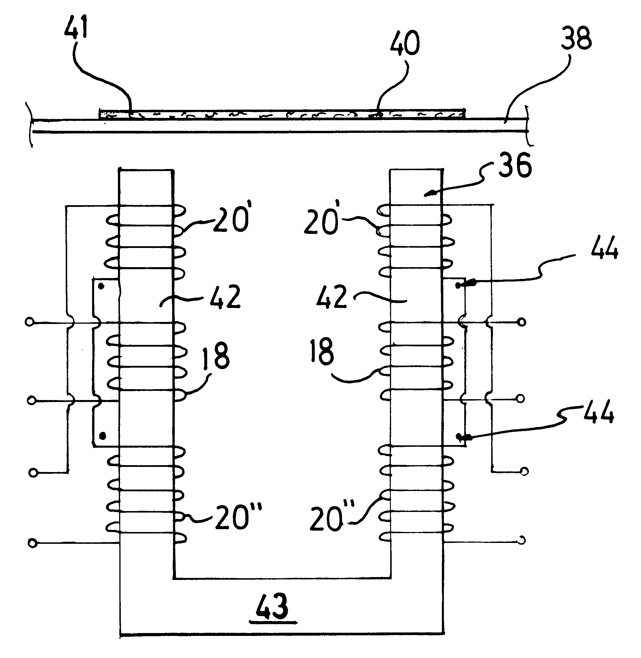
Referring to FIG. 8, drive coils 18 and detector coils 20' and 20" are arranged around a ferrite core 36. For use in a reproduction apparatus, the ferrite core 36 is positioned at a few mm from a glass platen 38. A security document 40 comprising elongated magnetic particles 41 is positioned on the glass platen. The ferrite core 36 is used to ensure a higher magnetic field at the level of the security document 40 for a given drive current.

The ferrite core 36 must not saturate in order to avoid from creating additional non-linearities and harmonics.

The ferrite core 36 is preferably U-shaped. This means it has two legs 42 connected by a "bridge" 43. The bridge 43 ensures that the flux flow is kept away from any neighbouring metal of the reproduction apparatus.

A drive coil 18 is wired somewhere in the middle of each leg 42. The detector coil is divided into two parts 20' and 20". One part 20' is wired at the side of the glass platen 38 around the leg 42, the other part 20" is wired at...


PUM


Abstract

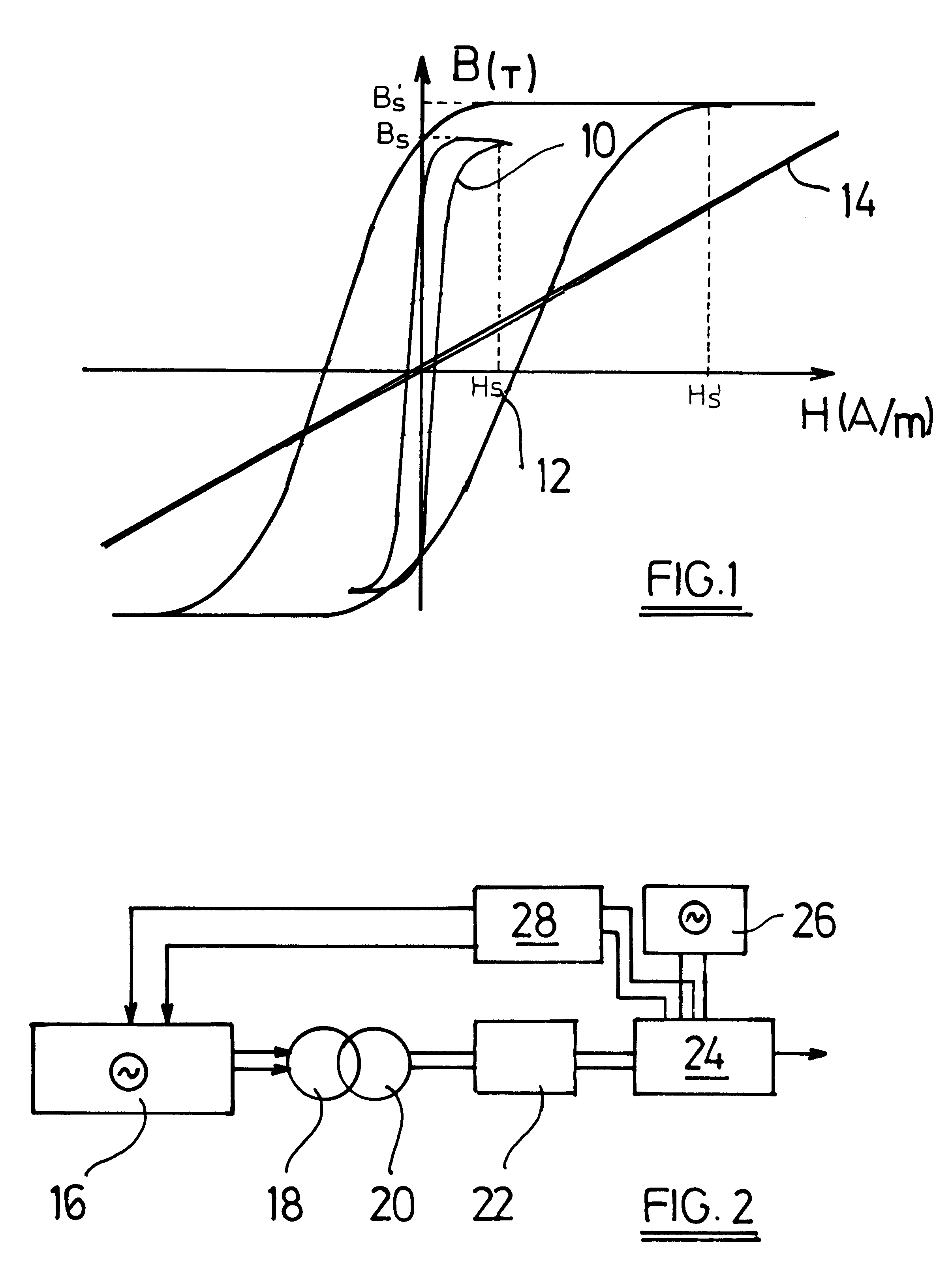
Apparatus for detecting the presence of magnetic elongated particles in a substrate, the base material of the substrate having magnetic properties substantially differing from the corresponding magnetic properties of the elongated particles. The elongated particles have such a long and thin form that their demagnetization factor N is smaller than {fraction (1 / 250)}, they have a diameter smaller than 30 micrometer, and they a magnetic saturation field greater than 100 A / m. Apparatus includes an emitter which emits an electromagnetic source signal of one or more particular base frequencies to the substrate (e.g., so that any magnetic elongated particles present go into a non-linear part of a B-H curve for at least part of cycle of the source signal). Apparatus also includes a detector that detects an electromagnetic detection signal emanating from the substrate for examining the detection signal for the presence of particular higher harmonics of the base frequencies or of any linear combination of the base frequencies or of the harmonics, particular higher harmonics being indicative of the presence of the magnetic elongated particles.

Description

The present invention relates to an apparatus for detecting the presence of particles in a substrate the base material of which has electromagnetic properties substantially differing from the corresponding electromagnetic properties of the particles.The invention is intended primarily to be used in the identification or authentication of all type of security documents having a paper or synthetic base material such as bank notes, cheques, passports, credit-cards, tickets, lottery-tickets and bonds which comprise the above particles, but it is also applicable to other applications in which objects need to be recognised.The prior art has already dealt in an extensive way with the identification of security documents.Some prior art solutions go in the direction of recognition of possible characteristic patterns printed at the surface of some security documents.In order to prevent genuine security documents from being falsely copied by means of high-resolution colour photocopying apparat...

Claims


Application Information

Patent Timeline
Patent Type & Authority Patents(United States)
IPC IPC(8): G07D7/04G07D7/00G07F7/08G06K7/08
CPCG06K7/084G07F7/086G07D7/04
Inventor ROBERTSON, PAULFISHER, JOHNBURRELL, JON
Owner NV BEKAERT SA
Learn More