Heating apparatus for vehicle

Inactive Publication Date: 2001-07-17
DENSO CORP
View PDF6 Cites 12 Cited by
  • Summary
  • Abstract
  • Description
  • Claims
  • Application Information

AI Technical Summary

Problems solved by technology

However, in a vehicle having a diesel engine or a lean burn engine, the passenger compartment cannot be sufficiently heated by cooling water of the engine.
In the heating apparatus, because the lever for changing the throttle state of the throttle member is manually operated, the lever operation is tro

Method used


Image

  • Heating apparatus for vehicle
  • Heating apparatus for vehicle
  • Heating apparatus for vehicle

Examples


first embodiment

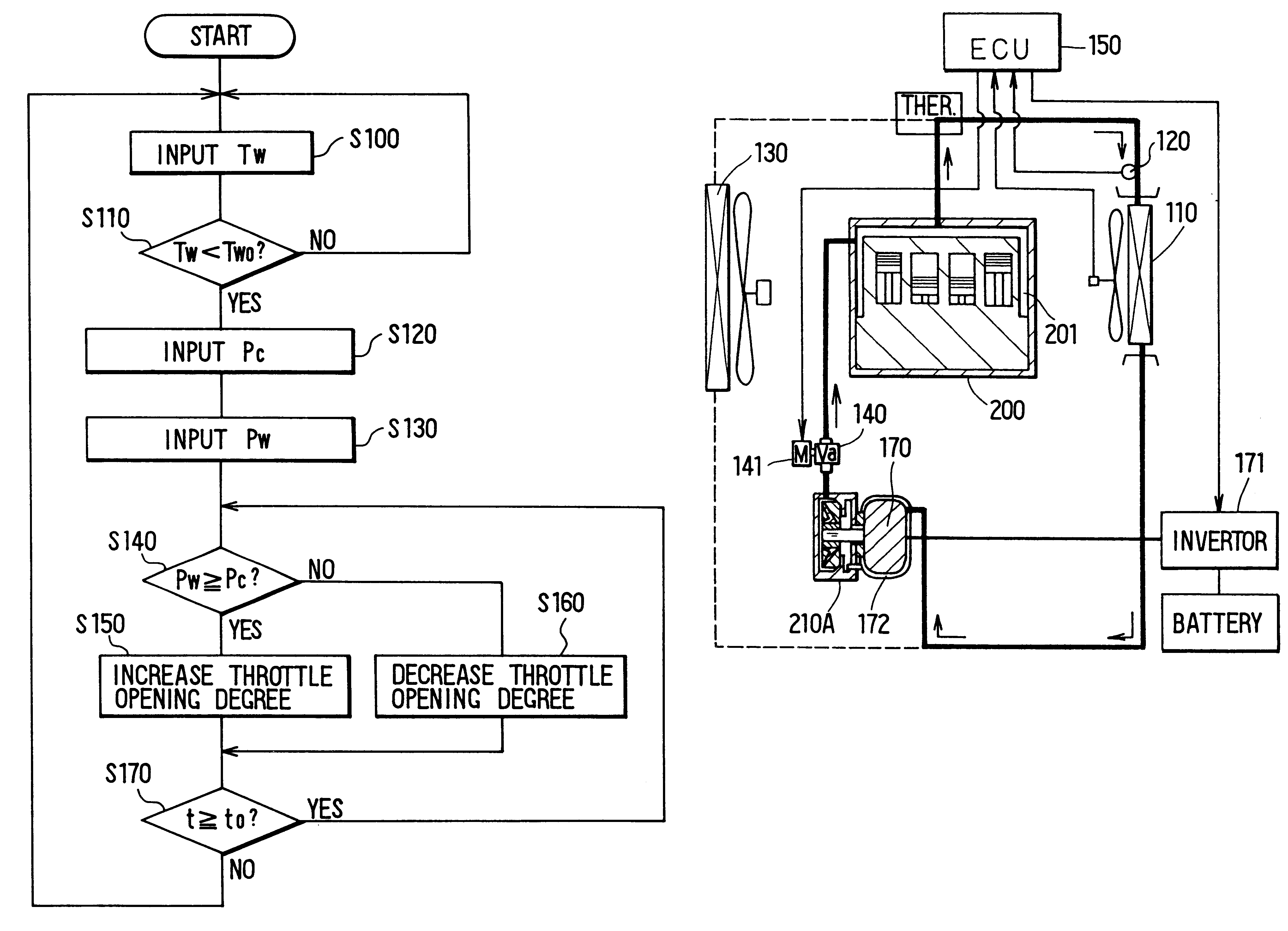
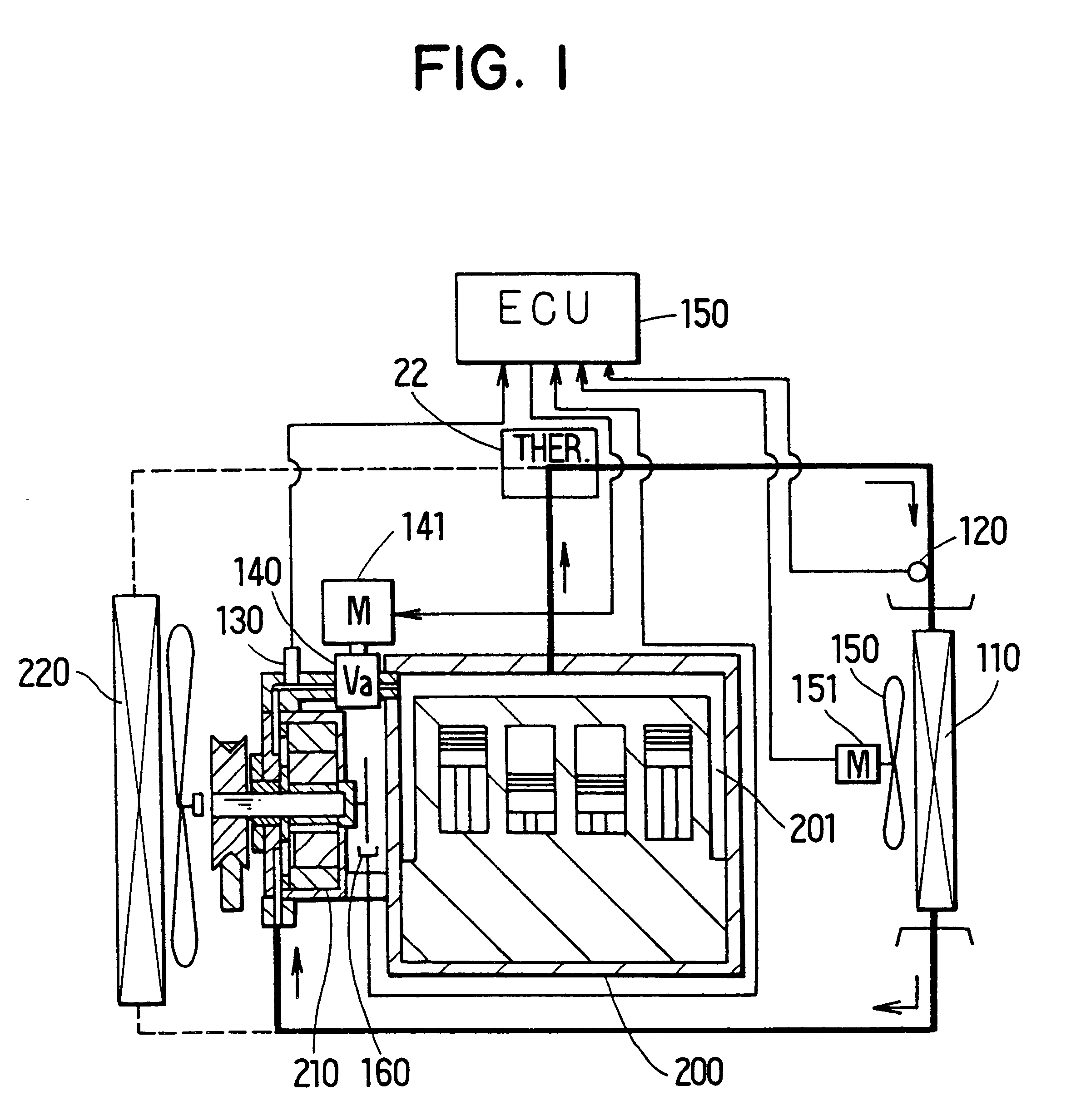
In the first embodiment, air is blown toward the heater core 110 by a blower 152, and the blower 152 is operated by an electrical motor 151. voltage applied to the electrical motor 151, signals from the sensors 120, 130, and a rotation speed Np of the pump 210, detected by a rotation sensor 160, are input into the ECU 150. Therefore, the ECU 150 calculates based on a pre-set program, and outputs signals to control the blower 152, the throttle valve 140 and the pump 210.

Next, operation of a heating apparatus for a vehicle according to the first embodiment of the present invention will be now described. The operation of the throttle valve 140 is controlled in accordance with the flow diagram shown in FIG. 3, and a target pressure Pc for controlling the throttle valve 140 is calculated based on the flow diagram shown in FIG. 4.

As shown in FIG. 3, when a heating switch (not shown) for the heating apparatus is turned on after the engine 200 is operated, water temperature Tw detected by t...

second embodiment

In the second embodiment, the opening degree of the throttle valve 140 and the flow amount of water passing through the throttle valve 140 are controlled based on the necessary heating quantity Q of the heating apparatus. That is, the flow amount of water discharged from the centrifugal pump 210A and the rotation speed Np of the centrifugal pump 210A are controlled based on the necessary heating quantity Q. According to the necessary heating quantity Q of the heating apparatus, a corresponding opening degree K1 of the throttle valve 140 is obtained based on the graph shown in FIG. 10, and a corresponding rotation speed Np of the pump 210A is also obtained based on graph shown in FIG. 9.

Next, the control of the throttle valve 140 according to the second embodiment of the present invention is performed based on the flow diagram shown in FIG. 11. When the heating switch of the heating apparatus is turned on after the engine 200 is operated, the water temperature Tw detected by the temp...

fourth embodiment

Next, operation of the heating apparatus according to the present invention will be now described. Here, operations of the switching valve 190 and the electromagnetic clutch 101 are mainly described.

(1) FIRST MODE

The first mode shown in FIG. 15 is set, when the rotation speed of the engine 200 is lower than a predetermined speed (e.g., idling rotation speed, in the fourth embodiment) during a heating operation. For example, the heating operation is performed when the temperature of outside air is low in the winter, or when the heating switch is turned on. During the first mode, the electromagnetic clutch 101 is turned on so that the driving force of the engine 200 is transmitted to the second pump 100, and throttle control of the throttle valve 140 is performed. Further, the switching valve 190 is operated to a first position shown in FIG. 15 so that cooling water flowing from the engine 200 flows into the suction side of the second pump 100. That is, when the switching valve 190 is...


PUM


Abstract

A heating apparatus for a vehicle includes a pump for circulating cooling water in a cooling water circuit, a heating heat exchanger for heating air blown into a passenger compartment of the vehicle using cooling water as a heating source, and a throttle valve disposed at a discharge side of the pump. In the heating apparatus, when the temperature of cooling water is low and heating capacity for heating the passenger compartment is insufficient, an opening degree of the throttle valve is reduced by a control unit. Therefore, heat is generated from the throttle valve and the pump so that the temperature of cooling water is increased. Thus, heating capacity of the heating apparatus can be improved without using a manual operation.

Description

This application is related to and claims priority from Japanese Patent Application No. Hei. 10-94875 filed on Apr. 7, 1998, No. Hei. 11-20521 filed on Jan. 28, 1999, and No. Hei. 11-59255 filed on Mar. 5, 1999, the contents of which are hereby incorporated by reference.1. Field of the InventionThe present invention relates to a heating apparatus for a vehicle. The heating apparatus is suitable for a vehicle having a diesel engine or a lean burn engine, for example.2. Description of Related ArtIn a conventional heating apparatus for a vehicle, a passenger compartment is heated using cooling water for cooling an engine of the vehicle as a heating source. However, in a vehicle having a diesel engine or a lean burn engine, the passenger compartment cannot be sufficiently heated by cooling water of the engine.To overcome this problem, in a heating apparatus disclosed in JP-U-63-50713, a pump is operatively linked with a vehicle wheel, a throttle member is disposed at a fluid-discharge p...

Claims


Application Information

Patent Timeline
IPC IPC(8): B60H1/03B60H1/02F01P3/20F01P5/00F01P5/12B60H1/08
CPCB60H1/03F01P3/20F01P2005/125F01P2060/18F01P2037/02F01P2060/08F01P2023/08
Inventor MORIKAWA, TOSHIOITO, HAJIMEAOKI, TOSHINAOONIMARU, SADAHISAINAGAKI, MITSUOMATSUI, HIROHITOTSUNOKAWA, MASARU
Owner DENSO CORP
Why Eureka
Try Eureka