
System and method for generating and using stage-based constraints for timing-driven design

a technology of stage-based constraints and timing analysis, applied in the field of system and method for generating and using stage-based constraints for timing-driven design, can solve the problems of complex timing analysis techniques that cannot be used in very large designs, techniques will reach their limits in performance and capacity, and the interpretation accuracy of complex timing analysis techniques is difficult to achiev

Inactive Publication Date: 2001-07-17
CADENCE DESIGN SYST INC
View PDF7 Cites 32 Cited by
  • Summary
  • Abstract
  • Description
  • Claims
  • Application Information

AI Technical Summary

Benefits of technology

Stage-based constraints provide a complete and accurate representation of nearly all of the system level timing constraints in common use today, are relatively compact, and are very simple to interpret.
Compared with existing approaches for timing-driven placement, routing, and incremental logic optimization, stage-based constraints scale much better with design size and avoid the need to embed full timing analysis engines in every tool.
Relative to detailed path constraints, stage-based constraints: (1) provide complete coverage and preserve the full semantics of the system-level constraints; (2) are sufficient for driving incremental logic optimization; (3) result in much faster run times for timing-driven placement and routing; (4) have a significantly smaller file size; (5) require less memory to interpret; and (6) are much faster to generate.
Relative to 3-pin constraints, stage-based constraints result in much faster run times for timing-driven placement and routing, and for incremental logic optimization, and have a significantly smaller file size
Stage-based constraints ensure consistency between tools by making it relatively easy to do consistent timing analysis.
They also provide consistency by explicitly incorporating clock slews and insertion delays (which then do not need to be recalculated in each tool with a likely loss in accuracy).

Problems solved by technology

System level constraints are very compact and provide full coverage of the timing constraints on the entire design, but they require complicated timing analysis techniques to interpret accurately.
However, the number of detailed path constraints required to provide reasonable coverage makes this approach unsuitable for very large designs.
Although existing techniques for passing timing constraints to placement and routing are well-established, we expect that in the near future these techniques will reach their limits in performance and capacity.
As designs of more than a million gates become common-place, the traditional approach based on detailed path constraints will run into problems with the amount of time required to generate the constraints, the file size needed to pass them from tool to tool, and the memory usage and CPU time required to interpret them.
Worse, each of the existing techniques for generating detailed path constraints suffers from a lack of coverage.
Some paths in the design go unconstrained, often because the number of path constraints is restricted to reduce their size, but also because the mechanisms for selecting the paths do not ensure that every path in the design is covered.
One popular path selection technique, used in the Synopsys Design Compiler "cover_design" method of generating detailed path constraints, still suffers from a coverage problem for paths through reconvergent logic.
Because of this lack of coverage, detailed path constraints are not suitable for driving incremental logic optimization.

Method used


Image

  • System and method for generating and using stage-based constraints for timing-driven design
  • System and method for generating and using stage-based constraints for timing-driven design
  • System and method for generating and using stage-based constraints for timing-driven design

Examples


Embodiment Construction

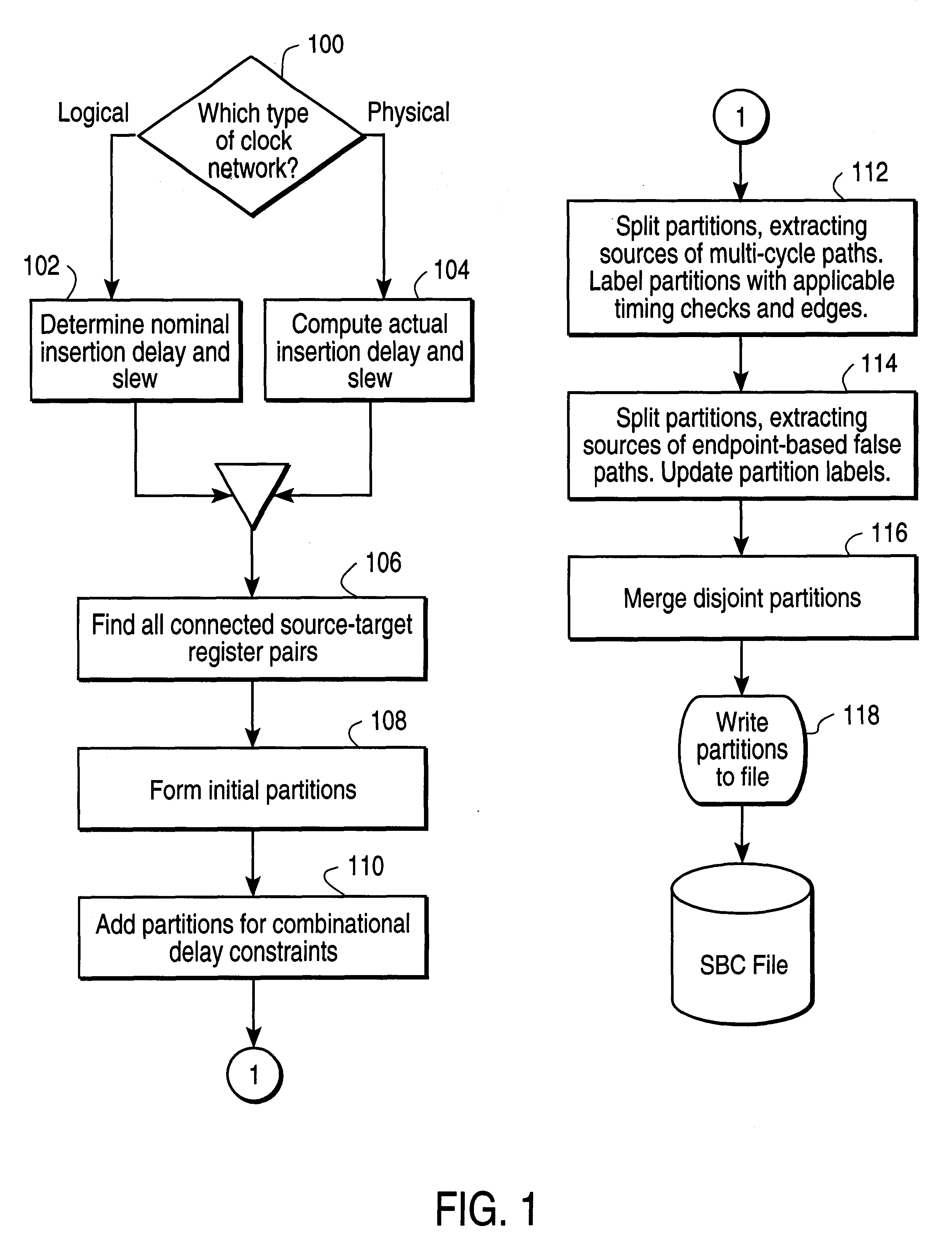
Some of the differences and advantages of the present invention are now set forth. A compact and accurate form of the timing constraints is the system level constraints entered by the designer, which include arrival / departure times, clock waveforms, false and multi-cycle specifications, and boundary conditions. All of this information is required in order to provide complete coverage of the constraints on the design.

However, interpreting these constraints directly requires full-blown timing analysis, which is complicated by the fact that the delay constraint on each path depends on the relationship between the clock waveforms at the source and target, as well as the setup and hold times of the target.

Clock waveforms are usually specified at the root of a clock distribution network. The position of the edges in each waveform are set to reflect offsets from a common implicit reference point, which provides a consistent frame of reference for calculations which relate clock waveforms.

C...


PUM


Abstract

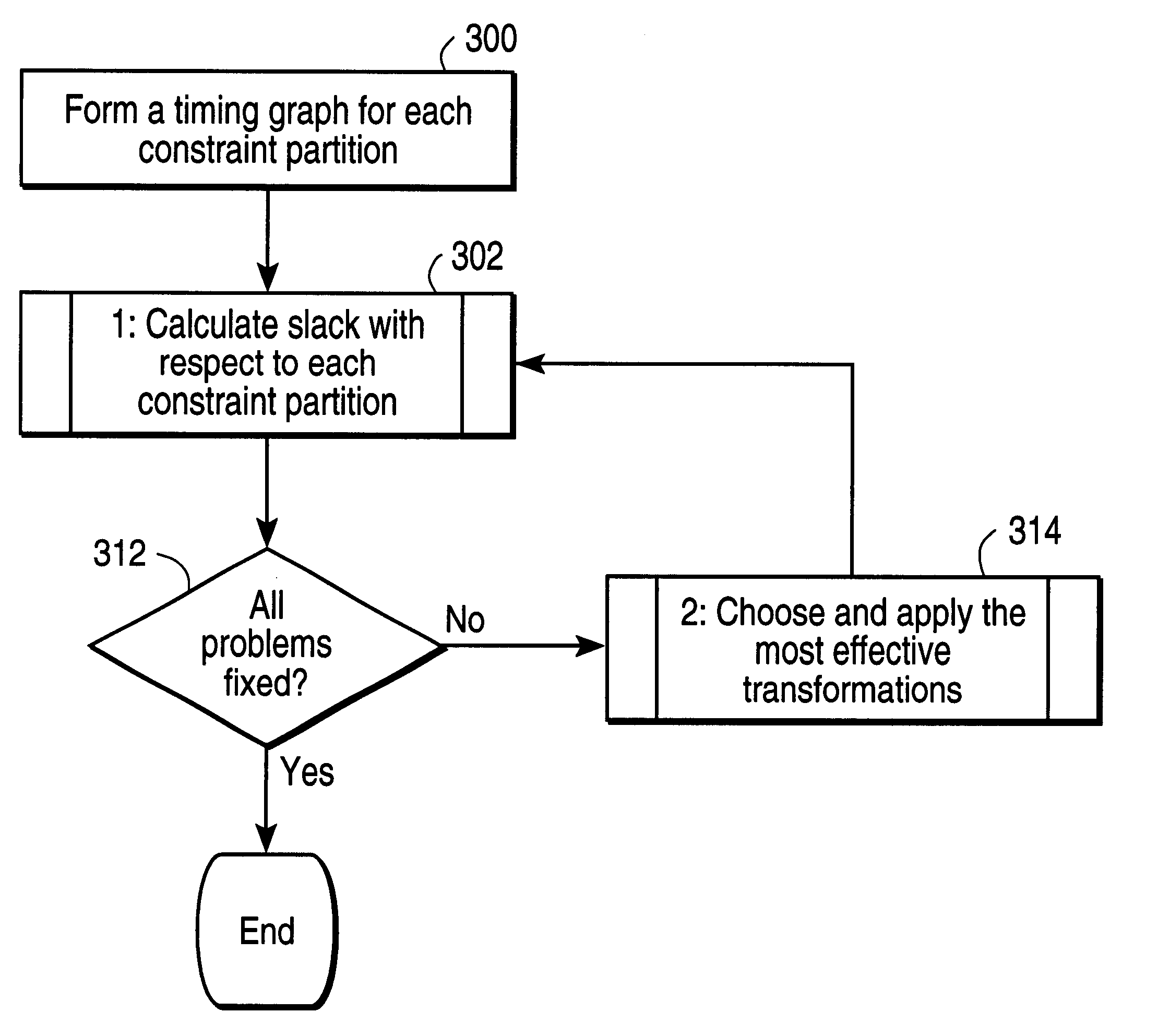
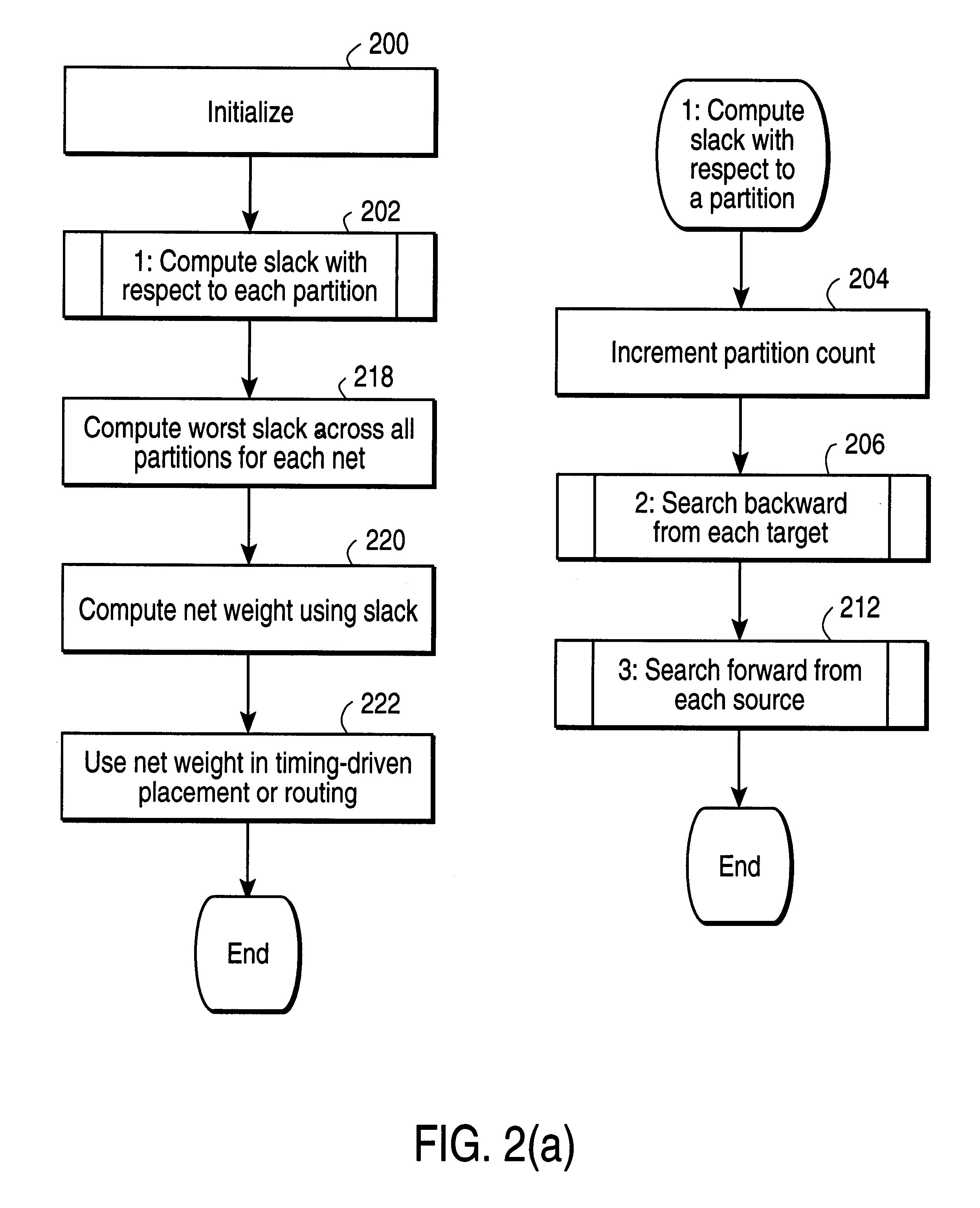
An integrated circuit design is divided into partitions which each contain two stages of information. The first stage corresponds to sources within the design, and the second stage corresponds to targets within the design. In one implementation, all of the sources in each partition are triggered by a common clock edge. In another implementation, all targets of each partition are triggered by a common clock edge. Specifying timing constraints in partitions can provide an efficient method of determining how much slack, if any, is present in the timing of a design.

Description

This invention pertains to the fields of generating and using constraints for timing-driven design of integrated circuits. More particularly, this invention relates to the generation and use of stage-based constraints for timing-driven design of integrated circuits.BACKGROUND OF INVENTIONTraditional methods for specifying the timing constraints on an integrated circuit design fall into two categories: system level constraints entered by the user, and detailed path constraints generated automatically from the system level constraints. System level constraints are very compact and provide full coverage of the timing constraints on the entire design, but they require complicated timing analysis techniques to interpret accurately. Detailed path constraints are straightforward to interpret, and have therefore been used extensively in timing-driven placement and routing tools. However, the number of detailed path constraints required to provide reasonable coverage makes this approach unsu...

Claims


Application Information

Patent Timeline
IPC IPC(8): G06F17/50
CPCG06F17/5031G06F30/3312
Inventor HAHN, MARK S.LAM, JIMMYHE, LIMINMORRISON, CHRIS
Owner CADENCE DESIGN SYST INC
Learn More