Method of controlling a screwing spindle

a technology of screwing spindle and screwing head, which is applied in the direction of caps, closures using caps, applications, etc., can solve the problems of damage to the stopper or the package neck, and achieve the effect of simplifying the regulation of the feed fluid pressur

Inactive Publication Date: 2001-07-24
SERAC GROUP
View PDF11 Cites 11 Cited by
  • Summary
  • Abstract
  • Description
  • Claims
  • Application Information

AI Technical Summary

Benefits of technology

An object of the invention is to propose a method of controlling a screwing spindle in a manner that enables the required tightening torque to be obtained accurately.
Two different pressures are used. Thus, once the tightening operation has been completed, the constant pressure that is lower than the tightening pressure can be used to return the actuator, thereby achieving significant fluid savings.
In this way, the spindle is set into rotation by pressure being applied thereto, and its kinetic energy is restored while pressure is not being applied thereto, thereby making it possible to control the speed of the spindle by acting on the pressure-on times and on the pressure-off times.
In this variant, it is advantageous for the differential pressure to have a value that is constant and equal to the tightening pressure.
As in the preceding case, only one pressure level is used, and it corresponds to the required tightening torque, thereby simplifying regulation of the feed fluid pressure.

Problems solved by technology

A problem comes from the fact that when the stopper begins to be screwed on, there is little friction between the stopper and the neck, such that there is little opposition to rotation of the spindle.
This dynamic torque can damage the stopper or the neck of the package, and it can make it necessary for a user of the package to have recourse to a tool for loosening the stopper.

Method used


Image

  • Method of controlling a screwing spindle
  • Method of controlling a screwing spindle
  • Method of controlling a screwing spindle

Examples


Embodiment Construction

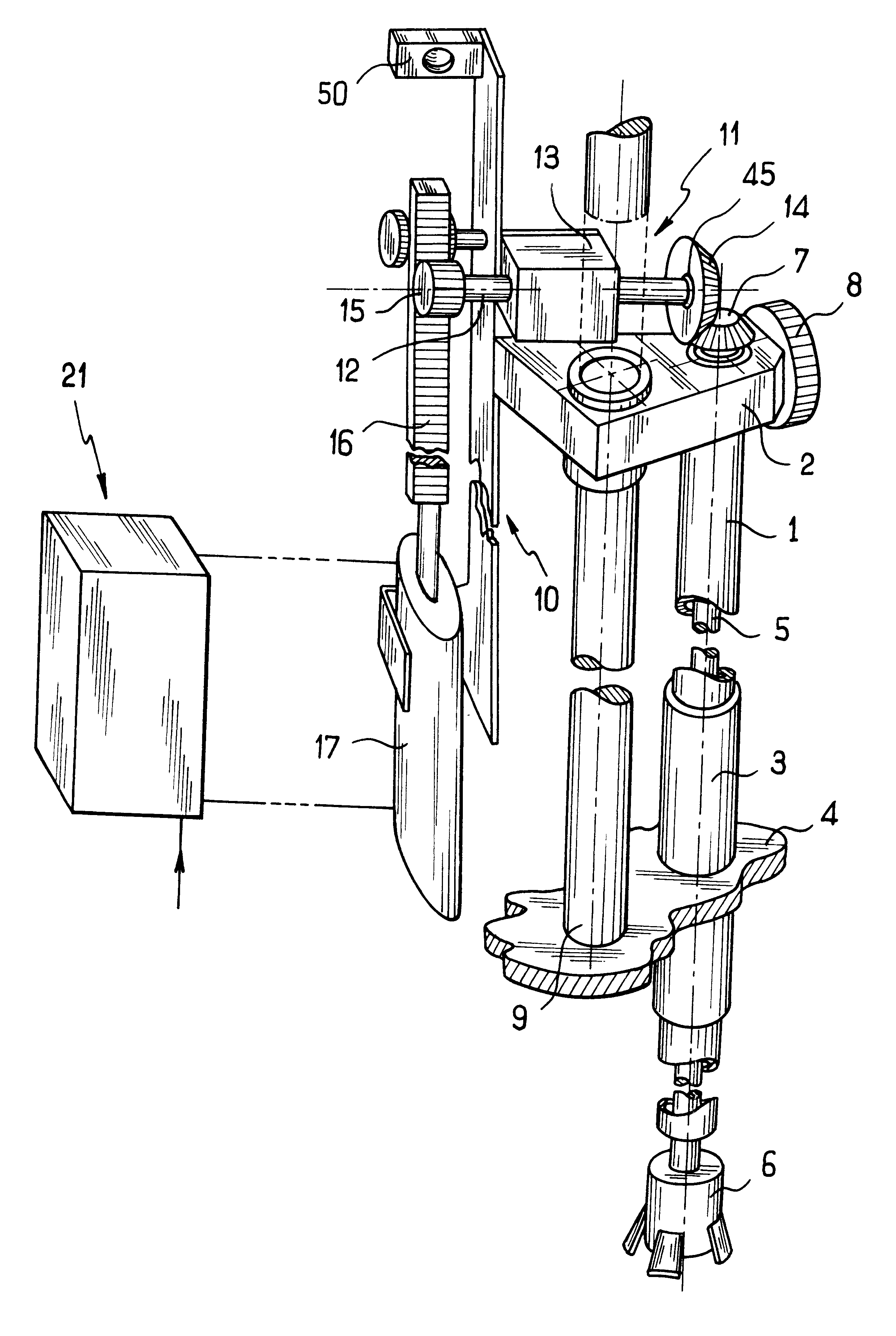
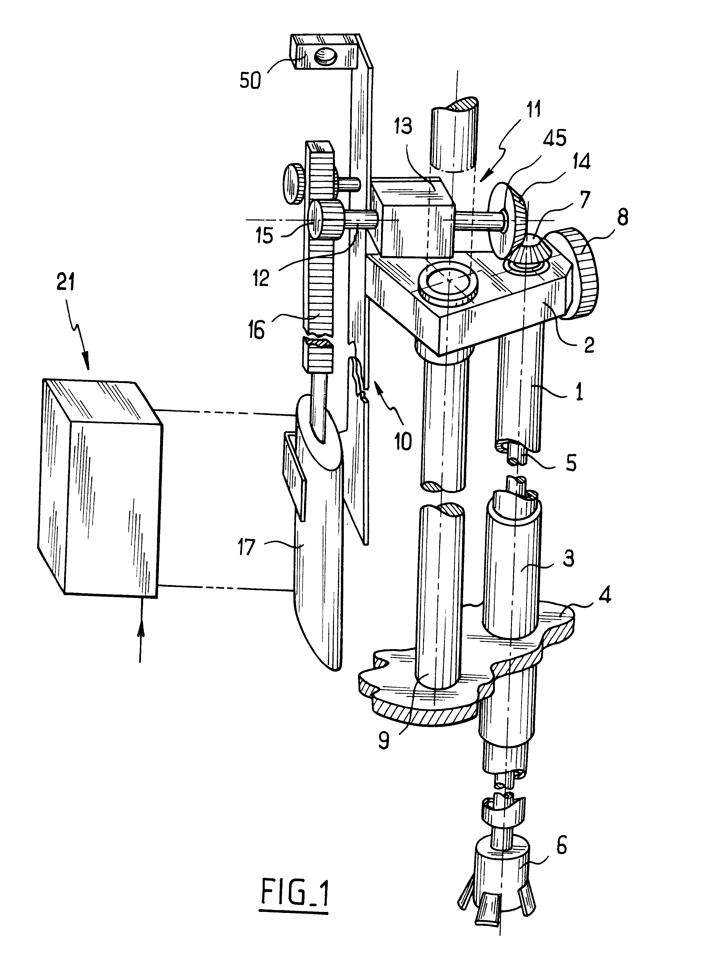
With reference to the figures, the tightening spindle controlled by the method of the invention is conventional in structure and operation, and certain elements thereof are not shown. In the embodiment that is shown, the spindle comprises a vertical guide tube 1 fixed to a spindle support 2 and sliding vertically in a sleeve 3 secured to a rotary platform 4. The tube 1 rotatably receives a spindle shaft 5 whose bottom end projects beyond the tube 1 and carries a stopper-engaging jawed chuck device 6. The top end of the spindle shaft 5 carries a conical gear wheel 7 co-operating with a drive assembly given overall reference 1.

The spindle support 2 is mounted to slide on a column 9 fixed to the rotary platform 4 and it carries a wheel 8 designed to co-operate with a cam of a stationary structure for positioning the support 2 and the parts associated therewith in the vertical direction.

A support plate 10 is fixed on the side of the spindle support 2 and carries the drive assembly 11.

Th...


PUM


Abstract

A method of controlling a screwing spindle comprising a fluid-fed motor and having a drive member connected to a spindle shaft to rotate it, the method comprising the step of feeding the screwing spindle under nominal conditions of pressure and flow rate that generate a required tightening torque, and a prior step during which the screwing spindle is fed under conditions that are weaker than the nominal conditions by a ratio that is sufficient to ensure that the spindle shaft has a speed of rotation that generates kinetic energy producing a torque that is less than the required tightening torque.

Description

The present invention relates to a method of controlling a screwing spindle of the kind used for screwing stoppers onto packages having threaded necks.Screwing spindles are known that have a linear actuator with a piston connected to a spindle shaft to rotate it. A method commonly used for controlling such spindles consists in subjecting the piston to differential tightening pressure, thereby generating the required torque for tightening the stopper on the neck of the package. A problem comes from the fact that when the stopper begins to be screwed on, there is little friction between the stopper and the neck, such that there is little opposition to rotation of the spindle. The spindle shaft thus acquires a high speed of rotation, and because of its inertia the spindle shaft stores a considerable amount of kinetic energy. The kinetic energy stored in this way causes the stopper to be tightened quickly until it comes into abutment, at which point the spindle shaft is caused to stop s...

Claims


Application Information

Patent Timeline
Patent Type & Authority Patents(United States)
IPC IPC(8): B67B3/20B67B3/00
CPCB67B3/2073
Inventor GRUSON, BERTRANDOVIEVE, GERARD
Owner SERAC GROUP
Why Eureka
Try Eureka