Lock-up damper of torque converter

a torque converter and lock-up mechanism technology, which is applied in the direction of rotary clutches, fluid couplings, gearing, etc., can solve the problems of reducing the total amount of stresses applied around the receiving openings, reducing the weight of the lock-up damper, and reducing the thickness of the output member. , the effect of reducing the thickness of the output member

Inactive Publication Date: 2001-07-31
EXEDY CORP
View PDF12 Cites 9 Cited by
  • Summary
  • Abstract
  • Description
  • Claims
  • Application Information

AI Technical Summary

Benefits of technology

, in accordance with the present invention, the weight of the lock-up damper can be reduced by providing holes or cutouts in the input member at radially outward positions of the receiving openings while stresses at the peripheral regions of the receiving openings are limited within an allowable stress range. The weight of the lock-up damper can also be reduced by providing openings circumferentially spaced between the receiving openings and reducing the thickness of the output member while stresses at the peripheral regions of the receiving openings are limited within an allowable stress range. As a result, the weight of the lock-up damper and, therefore, the weight of the torque converter can be respectively reduced without sacrificing their respective strengths.

Problems solved by technology

However, since these plates have the receiving windows for receiving the coil springs as described before, relatively high stresses are naturally occur around the receiving windows of the drive plate and the driven plate.
This results in vibrations being transmitted from the rotatable input body to the rotatable output body.
The presence of holes or cutouts may adversely reduce the rigidity at locations radially outward of the respective receiving openings, so that more stresses could be applied around the respective receiving openings from the elastic member.
As a result, the total amount of stresses applied around the receiving openings is not substantially increased.
Furthermore, since the annular continuous section is radially arranged between the holes or cutouts, which are provided for the purpose of weight reduction, and the receiving openings, which tend to have large stresses around them, the stresses around the receiving openings can be effectively limited.
The presence of the hole may adversely reduce the rigidity at the corresponding intermediate region between the adjacent receiving openings, so that more stresses could be applied around the respective receiving openings from the elastic member.

Method used


Image

  • Lock-up damper of torque converter
  • Lock-up damper of torque converter
  • Lock-up damper of torque converter

Examples


Embodiment Construction

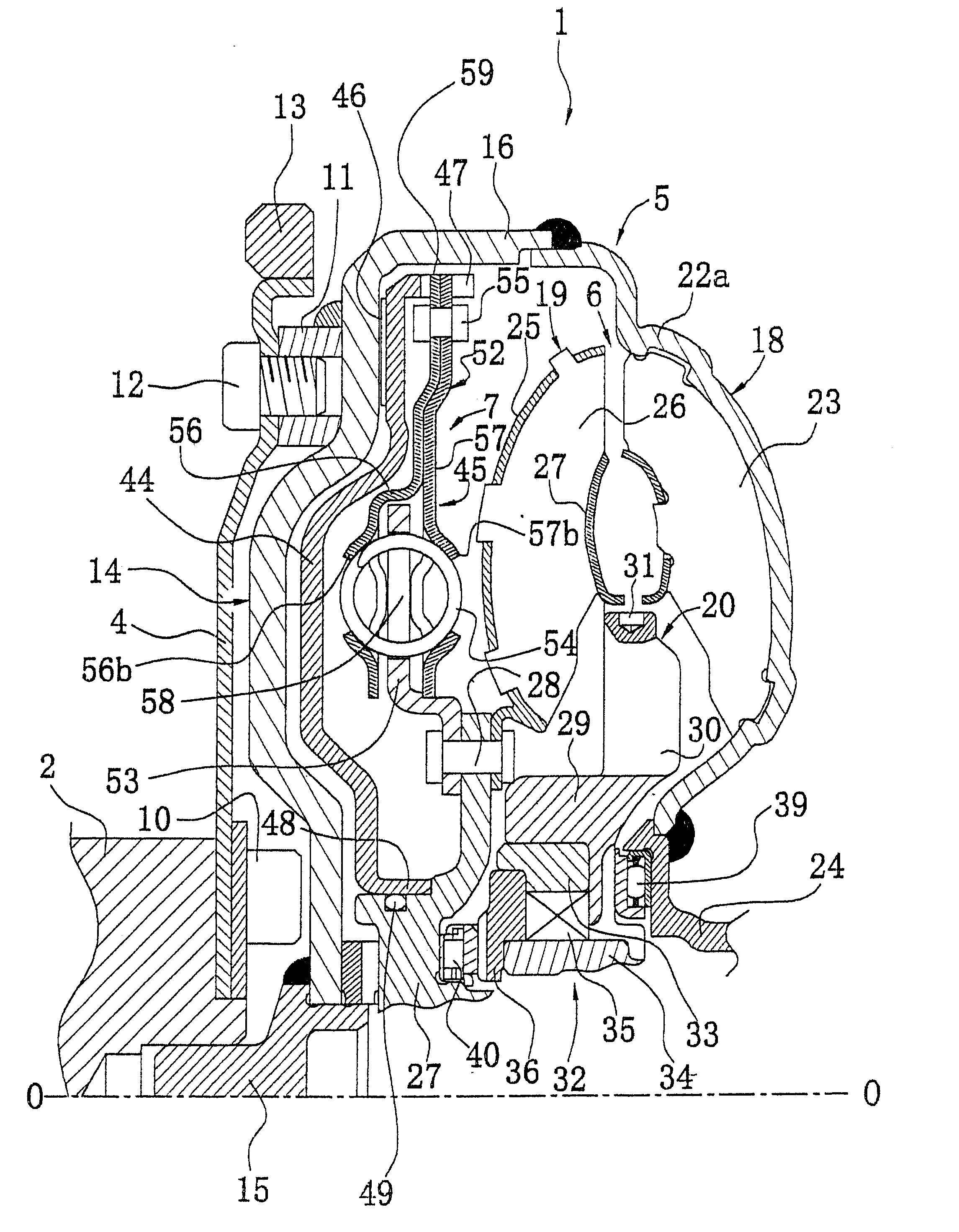
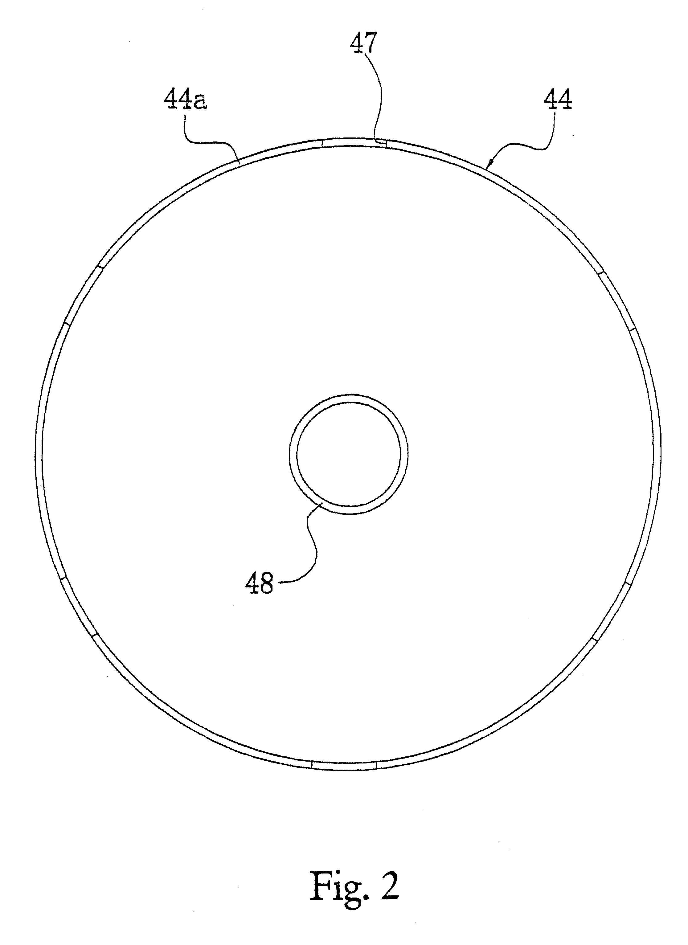
The clutch plate 56 and the retaining plate 57 both having a plurality of cutouts 56e and 57e are utilized in the above described first embodiment. However, a retaining plate 157 of FIG. 12 having a plurality of elongated holes (openings) 57g instead of the cutouts 57e and a clutch plate (not shown) having a plurality of elongated holes instead of the cutouts 56e can be alternatively utilized.

Since the structure of a clutch plate having a plurality of elongated holes is similar to that of the retaining plate 157 having the plurality of elongated holes 57g the structure of the clutch plate having the elongated holes will not be described or illustrated in detail herein.

The retaining plate 157 has a plurality of radially outwardly extending projections 57a along the outer peripheral region thereof. Preferably, the retaining plate 157 has six projections. Each projection 57a has a hole 57c through which a rivet 55 is received to attach the retaining plate 157 to a clutch plate via oppo...


PUM


Abstract

A lock-up mechanism 7 of a torque converter 1 has a piston 44 with a lock-up damper 45. The lock-up damper 45 includes a drive member and a hub flange 53 with the elastic members or torsion springs 54 operatively coupled therebetween to dampen vibrations in the torque converter 1. The drive member and the hub flange 53 both have a plurality of window holes 56d, 57d and 58 that are arranged circumferentially for receiving the corresponding torsion springs 54. The drive member includes a clutch plate 56 and a retaining plate 57. The clutch plate 56 of the drive member has a plurality of holes or cutouts 56e arranged radially outward of the window holes 56d. These holes or cutouts 56e are arranged to reduce the weight of the clutch plate 56, while maintaining the stresses around the window holes 56d of the clutch plate 56 within an allowable stress range. The retaining plate 57 of the drive member also has a plurality of holes or cutouts 57e that are arranged radially outward of the window holes 57d. These holes or cutouts 57e are arranged to reduce the weight of a retaining plate 57, while maintaining the stresses around the window holes 57d of the retaining plate 57 within an allowable stress range. The hub flange 53 of the lock-up damper 45 also include a plurality of holes or cutouts 59 that are circumferentially arranged between the window holes 58 in the hub flange 53. These holes or cutouts 59 are arranged to reduce the weight of a hub flange 53, while maintaining the stresses around the window holes 58 of the hub flange 53 within an allowable stress range.

Description

1. Field of the InventionThis invention generally relates to a lock-up mechanism of a torque converter. More specifically, the present invention relates to a lock-up damper arranged in a lock-up mechanism for mechanically transmitting torque from a rotatable input body to a rotatable output body of a torque converter.2. Background InformationIn general, the damper mechanism reduces vibrations transmitted from the rotatable input body to the rotatable output body, while transmitting torque from the rotatable input body to the rotatable output body. One example of such a damper mechanism is a damper arranged in a lock-up mechanism of a torque converter (hereinafter referred to as a lock-up damper).The torque converter is a device that has three types of runners (i.e., an impeller, a turbine and a stator) and normally transmits torque via hydraulic fluid. The impeller is secured to a front cover, which is connected to the rotatable input body. Torque of the impeller is transmitted to t...

Claims


Application Information

Patent Timeline
Patent Type & Authority Patents(United States)
IPC IPC(8): F16H45/02F16H45/00
CPCF16H45/02F16H2045/0294F16H2041/246
Inventor YAMAGUCHI, MITSUGUNAKAMURA, TAKEYUKIMIURA, HIDEKI
Owner EXEDY CORP
Why Eureka
Try Eureka