Device for grinding an end face, especially an annular surface at the edge of a workpiece bore

a technology of end face and workpiece, which is applied in the direction of grinding machines, edge grinding machines, grinding machines, etc., can solve the problems of limited space, device however, cannot be used for machining processes, and the shape precision and surface quality of high-precision workpieces are often unsatisfactory, so as to achieve minimal constructive height and high precision and quality of the machined surface.

Inactive Publication Date: 2001-07-31
MASCHFAB GEHRING +1
View PDF8 Cites 13 Cited by
  • Summary
  • Abstract
  • Description
  • Claims
  • Application Information

AI Technical Summary

Benefits of technology

The periodic displacement of the grinding tool transverse to the central axis of the guide pin allows a surface-machining of the end face of workpieces and also the generation of a chamfer at the edge of the workpiece bore with a planar grinding surface, the shape of which is thus not changed by wear and subsequent trueing or dressing operations so that in mass production a very high precision and quality of the machined surface can be achieved. The displacement movement can be realized within a small amount of space so that a minimal constructive height of the entire device results.

Problems solved by technology

Since grinding pads or coatings are in general inhomogeneous, the shape precision and the surface quality of the chamfer in mass production is often unsatisfactory for high-precision workpieces.
These devices however can not be used for machining processes with limited available space because of their relatively large size.

Method used


Image

  • Device for grinding an end face, especially an annular surface at the edge of a workpiece bore
  • Device for grinding an end face, especially an annular surface at the edge of a workpiece bore
  • Device for grinding an end face, especially an annular surface at the edge of a workpiece bore

Examples


Embodiment Construction

The present invention will now be described in detail with the aid of several specific embodiments.

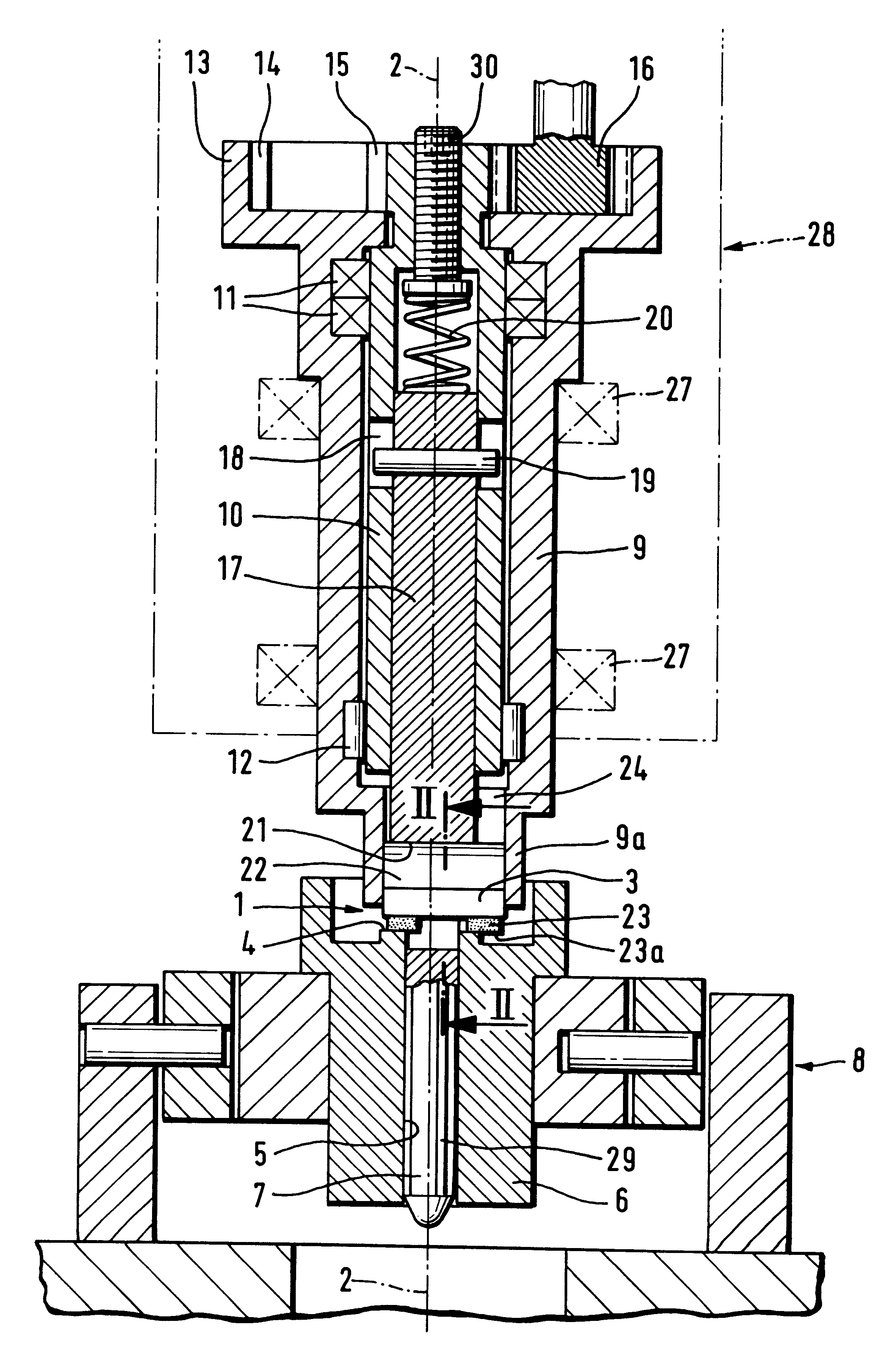
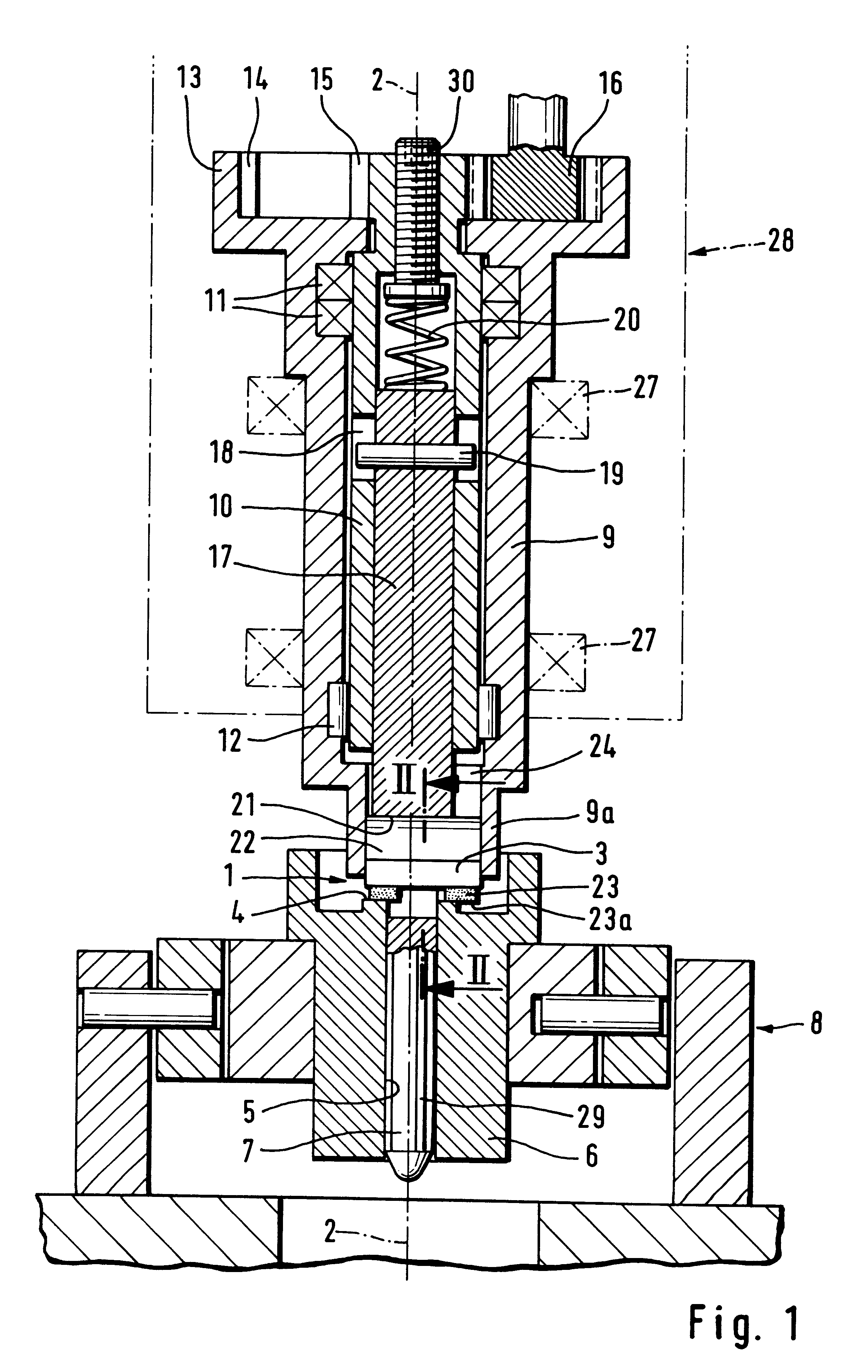
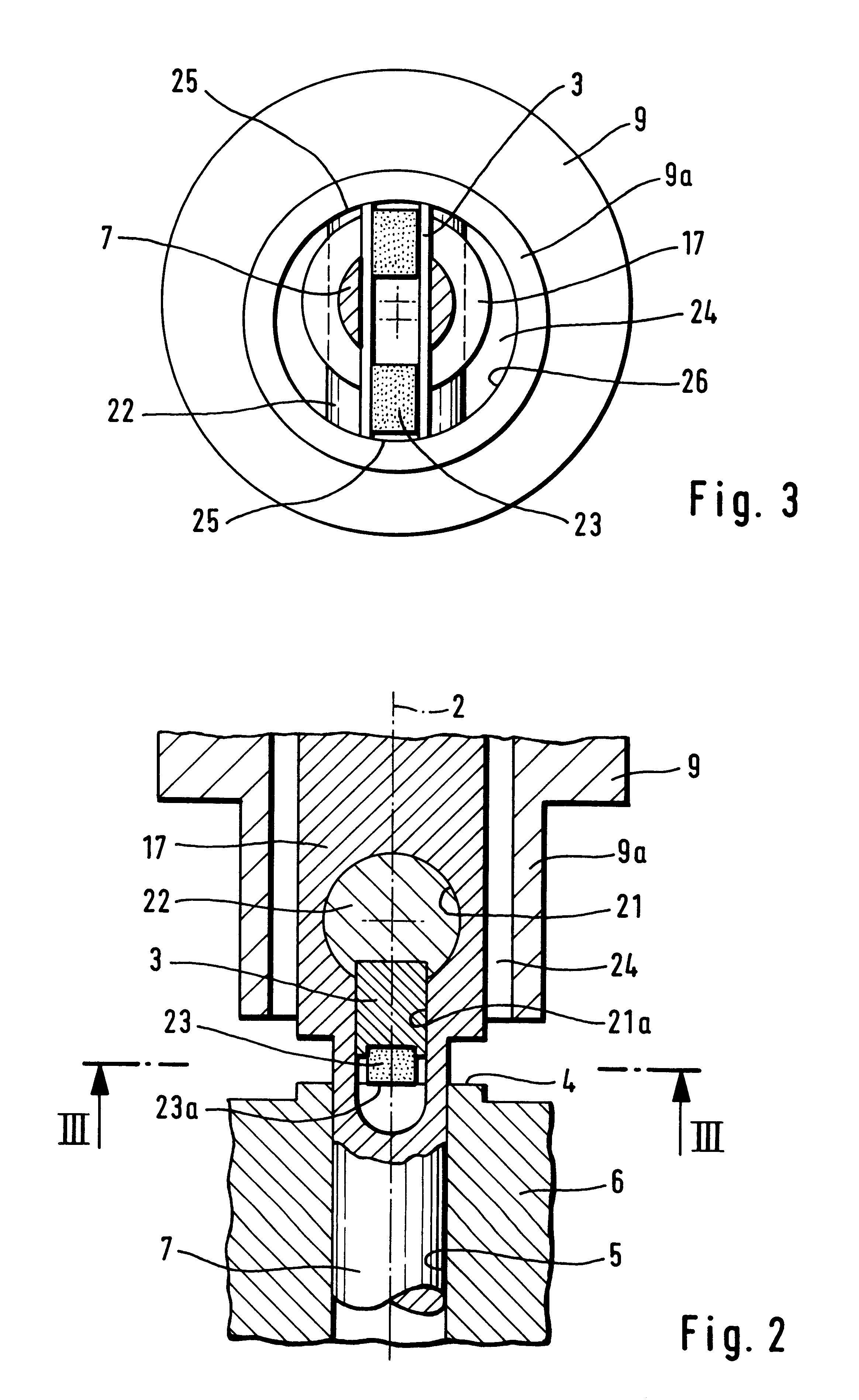
The device according to FIGS. 1-3 has a grinding tool that is embodied as a honing strip 3 with a grinding pad or coating 23 and that is secured to a holding device 22. The holding device 22 is a cylindrical slide into which the honing strip 3 is inserted parallel to its axis. The holding device or slide 22 is displaceable in a throughbore 21 of a shaft 17. The shaft 17 and the guide pin 7 form an integral part. The guide pin 7 is positioned in the bore 5 of the workpiece 6 which has been finish-honed. The workpiece 6 is supported in a manner known per se in the securing device 8 comprising a gimbal-type support for a workpiece clamping device so that the workpiece 6 is always precisely aligned with the aid of the guide pin 7 relative to the central axis 2 which coincides with the rotational axis of the shaft 17. The shaft 17 is the inner member of a telescopic drive shaft. The outer s...


PUM


Abstract

A device for grinding an end face at an edge of a workpiece bore of a workpiece has a driven grinding tool and a guide pin, connected to the grinding tool, for insertion into the workpiece. The guide pin is dimensioned so as to precisely match the workpiece bore. The guide pin has a central axis. The grinding tool has a grinding surface extending angularly to the central axis. The grinding tool is periodically displaceable transverse to the central axis.

Description

The present relates to a grinding device for grinding an end face, especially an annular surface, at the edge of a workpiece bore with a driven grinding tool, the grinding surface of which extends angularly relative to the axis of a guide pin which for a precise introduction into the machined (for example, honed) bore has an identical size (identical dimensions) and which is connected to the grinding tool.A known device of this kind is disclosed in German patent application 44 41 623 A1 and serves for fine machining a chamfer at the edge of a workpiece bore which serves as a sealing seat for a valve needle. Such valve bores are, for example, provided for injection pumps of combustion engines. They have a very small diameter of only a few millimeters and must be machined very precisely. The end face forming the edge of the bore and surrounding the bore of the workpiece must also be machined very precisely. For grinding or other surface machining of a chamfer, it must be taken into co...

Claims


Application Information

Patent Timeline
Patent Type & Authority Patents(United States)
IPC IPC(8): B24B15/00B24B15/02B24B33/02B24B33/055B24B33/00B24B9/00
CPCB24B15/02B24B33/055B24B33/025
Inventor KLINK, ULRICHSTAMPFER, RICHARDSCHMIDT, HERMANNAULICH, DIETERWOLFGRAMM, JORG
Owner MASCHFAB GEHRING
Why Eureka
Try Eureka