

Chip antenna and radio equipment including the same
a technology of radio equipment and antennas, applied in the direction of resonant antennas, thermal imaging, protective materials, etc., can solve the problem of narrowing of the bandwidth bw
- Summary
- Abstract
- Description
- Claims
- Application Information
AI Technical Summary
Problems solved by technology
Method used
Image

Examples
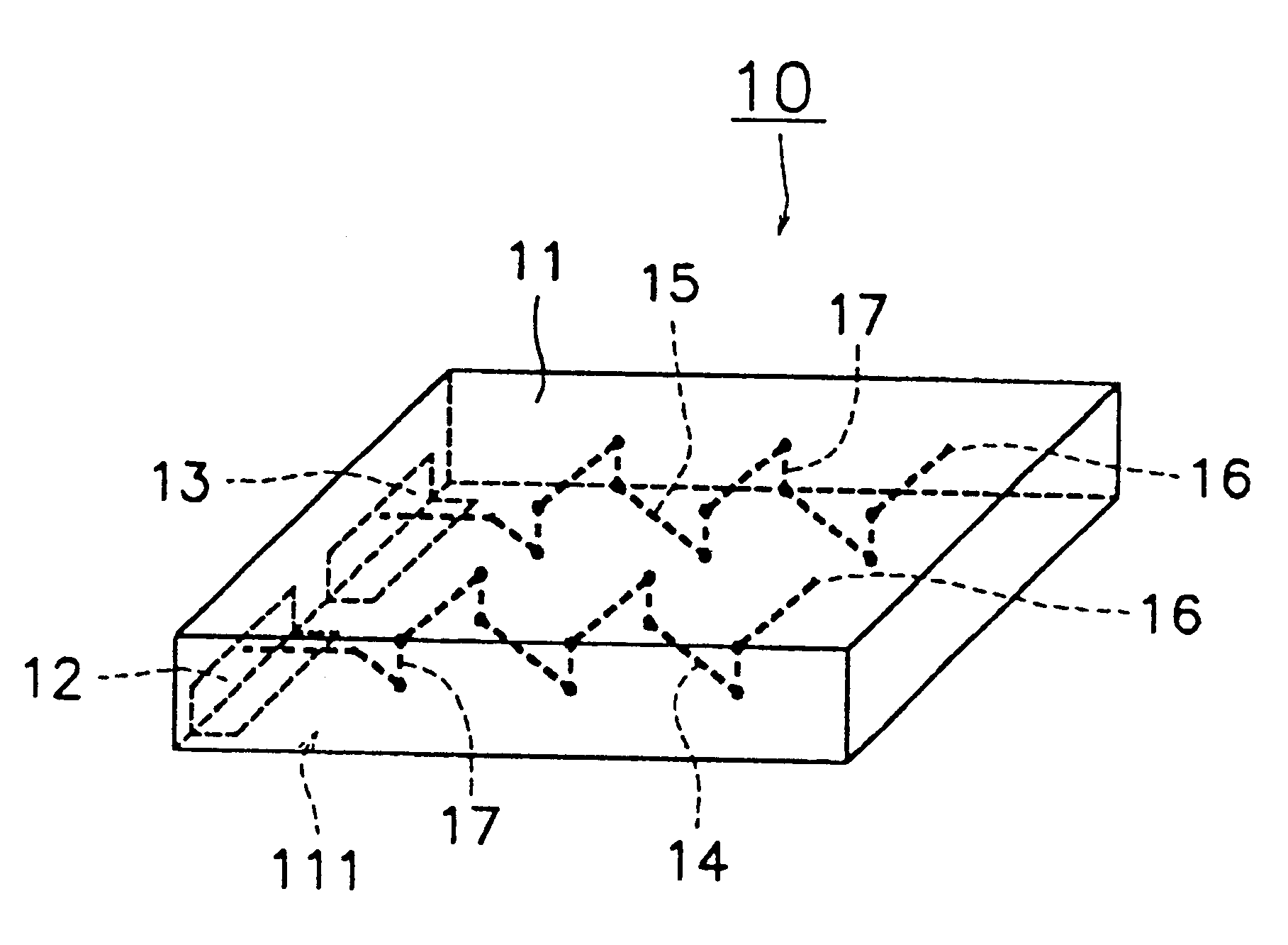
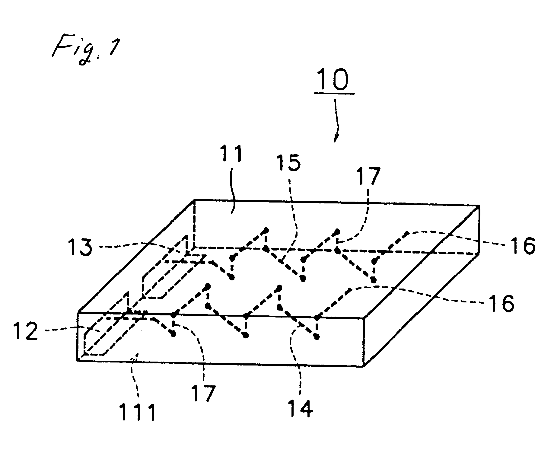
first embodiment
According to the above described chip antenna of the first embodiment, as the first conductor, one end of which is connected to the feeding terminal and the second conductor, one end of which is connected to the grounding terminal, are formed so as to be close to each other, leakage current is generated from the first conductor and the leakage current flows through the second conductor.
Therefore, as the first conductor and second conductor resonate at the same time because of the leakage current, only the feed to the first conductor causes the chip antenna to have a plurality of resonance frequencies, which makes it possible for the chip antenna to be small-sized, of broad bandwidth and of low power dissipation.
Further, in the embodiment of FIG. 1, because the first and second conductors are spirally disposed, the inductance values of the first and second conductors are able to be easily adjusted by adjustment of the pitch of the coil of the first conductor and the pitch of the coil...
second embodiment
According to the above described chip antenna of a second embodiment, because the free terminal to which the other end of the second conductor is connected is provided on the surface of the basic body, the capacitance generated between the second conductor of the chip antenna and the ground of the radio equipment mounted with the chip antenna is able to be enlarged.
In consequence, as clearly seen from Equations (1) and (2), it becomes possible to lower resonance frequencies f and broaden bandwidth BW.
FIG. 7 is an exploded perspective view of a third preferred embodiment of a chip antenna according to the present invention. The chip antenna 30 comprises a basic body 11 of a rectangular solid, a feed terminal 12 and a grounding terminal 13 provided on the surface of the basic body 11, and first and second conductors 14, 15 spirally arranged inside the basic body 11.
The effective length of the first conductor 14 is illustratively 64.9 mm. One end of the first conductor 14 is led to the...
third embodiment
According to the above-mentioned chip antenna of a third embodiment, because the first and second conductors are formed so as to be parallel to each other, the first and second conductors are able to be formed so as to be enlarged, and accordingly, the line length of the first and second conductors can be increased.
Therefore, because the inductance values of the first and second conductors are able to be increased, as clearly understood from Equations (1) and (2), it is possible to lower resonance frequencies f and broaden bandwidth BW.
FIG. 11 shows radio equipment mounted with one of the chip antennas 10, 10a, 20, 20a, 30, 30a shown in FIG. 1, FIG. 4, FIGS. 5 through 7, FIG. 9. The radio equipment, for example, a portable telephone terminal 40, is a circuit board 42 mounted with the chip antenna 10 on one main surface having a ground pattern 41 of the circuit board 42 arranged inside an enclosure 43, and transmits and receives an electronic radio wave through the chip antenna 10. T...
PUM
 Abstract
Description
Claims
Application Information