Control of magnetic direction in multi-layer ferromagnetic devices by bias voltage

a ferromagnetic device and bias voltage technology, applied in the field of control of the magnetization direction of multi-layer ferromagnetic devices, can solve the problems of usefulness affecting the overall efficiency of the magnetic device, so as to achieve the effect of improving the sensitivity and increasing the resolution of the flat panel display

Inactive Publication Date: 2001-08-07
UCHICAGO ARGONNE LLC
View PDF5 Cites 66 Cited by
  • Summary
  • Abstract
  • Description
  • Claims
  • Application Information

AI Technical Summary

Benefits of technology

It is yet another object of this invention to provide an improved system for controlling the magnetization direction of a ferromagnetic device wherein the use of the system permits smaller structures to be used with improved sensitivity.
It is yet another object to this invention to provide a novel system for controlling the magnetization direction of included ferromagnetic layers without requiring that one of the ferromagnetic layers have fixed its direction and magnetization.
It is still another object to this invention to provide an improved system for controlling the magnetization direction of the included ferromagnetic layers that can be used in developing increased resolution for flat panel displays.

Problems solved by technology

Although such systems are reasonably useful, they have several significant limitations.
For example, it is extremely difficult, if not impossible, to localize an external magnetic field to a high degree.
By not being able to localize the magnetic field, the overall efficiency and usefulness of the magnetic devices is hindered when used in applications such as magnetic sensors, digital read heads and nonvolatile memory devices.
There have been attempts to create different types of ferromagnetic devices with improved qualities but these have their drawbacks.
Unfortunately, however, this device still relies upon the presence of an external magnetic field to operate successfully.

Method used


Image

  • Control of magnetic direction in multi-layer ferromagnetic devices by bias voltage
  • Control of magnetic direction in multi-layer ferromagnetic devices by bias voltage
  • Control of magnetic direction in multi-layer ferromagnetic devices by bias voltage

Examples


Embodiment Construction

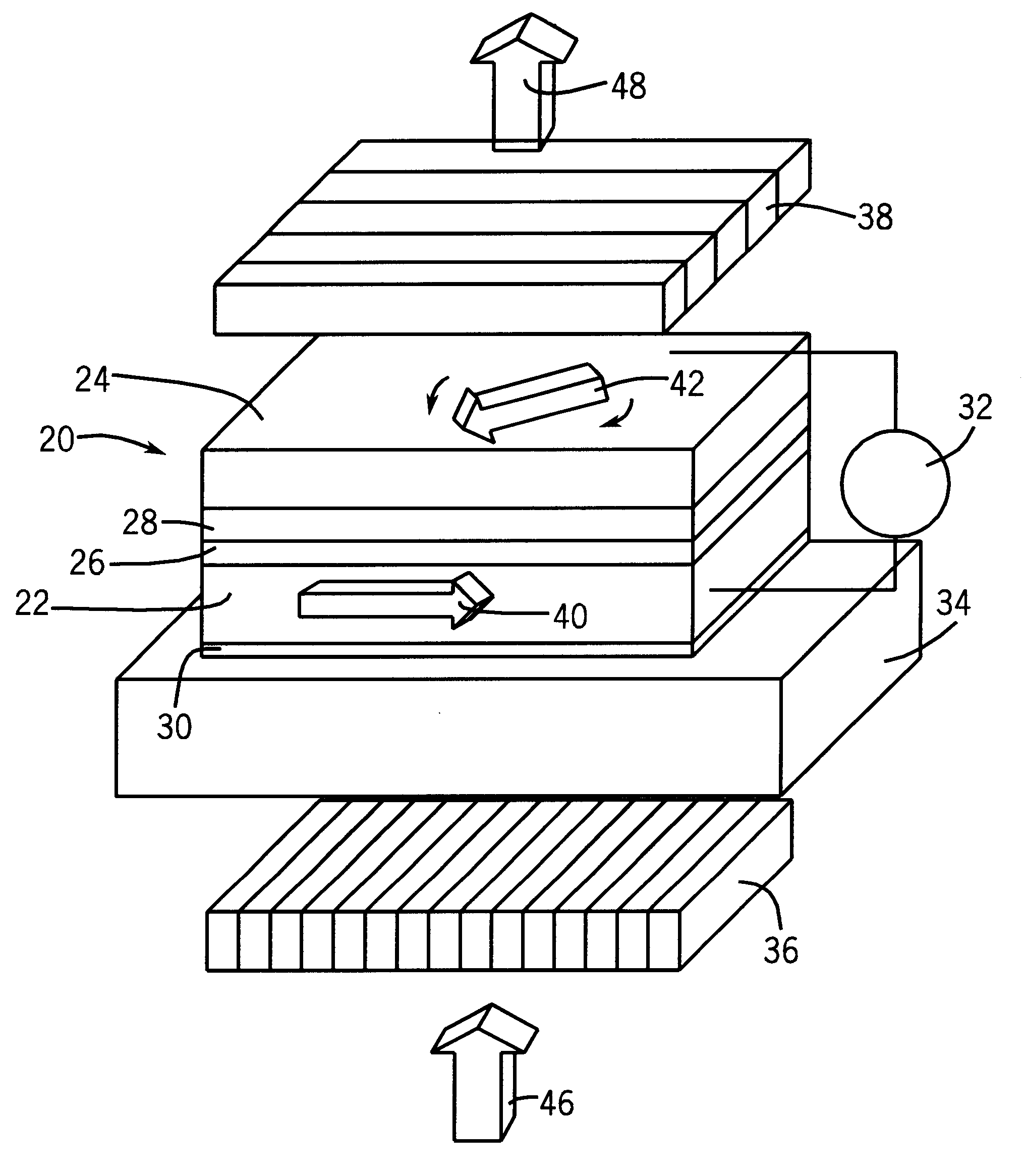
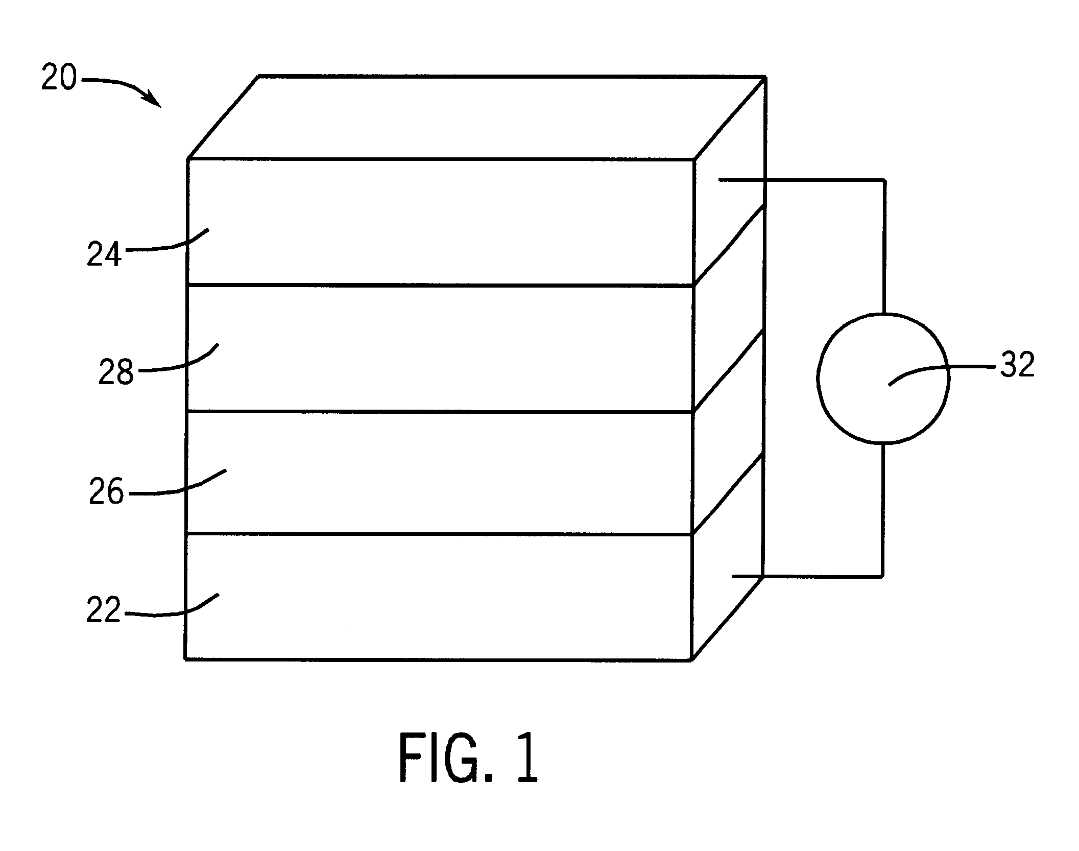
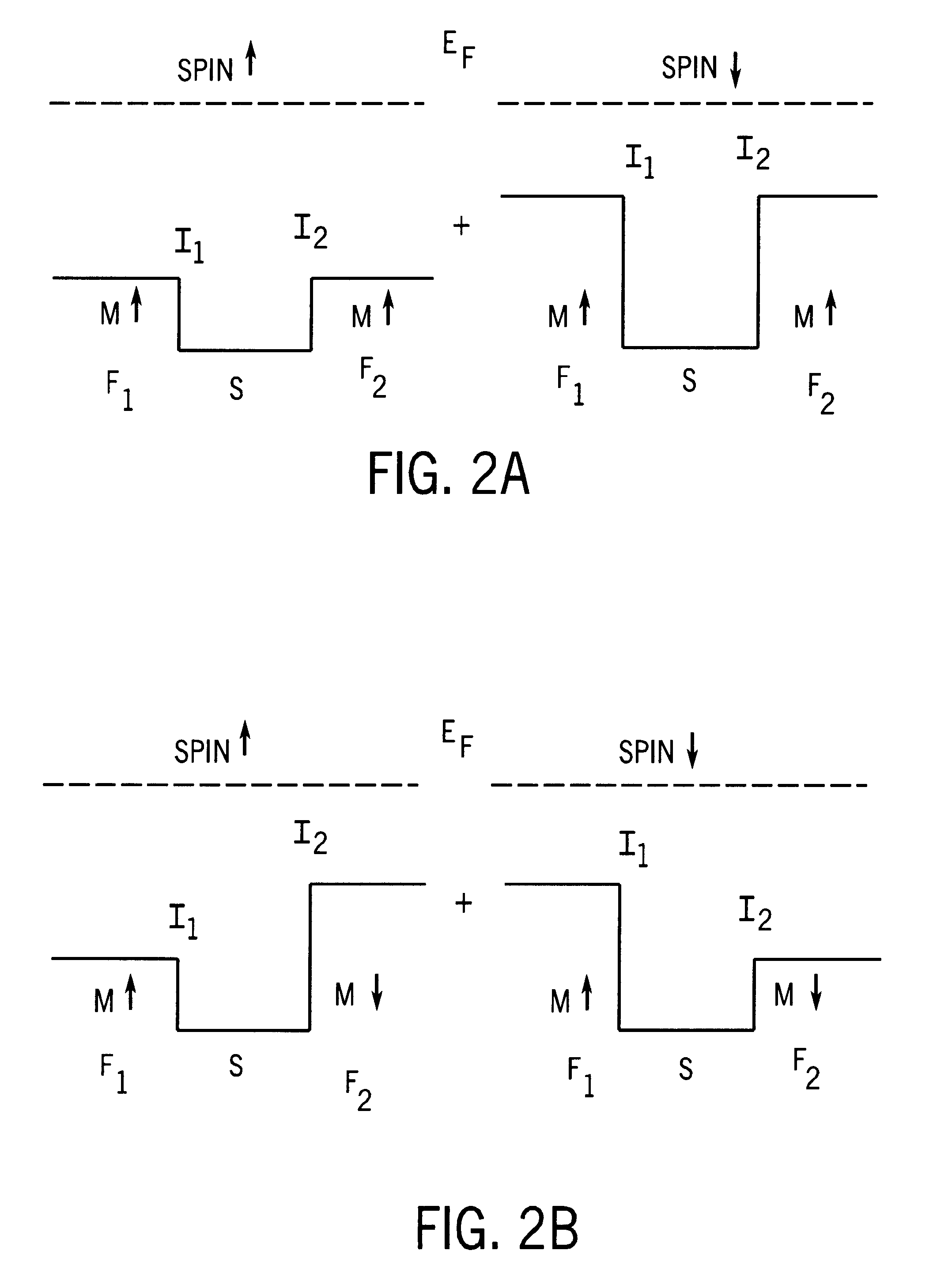
In order to illustrate embodiments of the invention, an explanation is provided to describe the methodology and function first for a prior art interlayer exchange coupling methodology and then the interlayer exchange coupling concept of the present invention. Although the manner in which the phenomena is described is one rigorous approach which explains the operation of the invention for those skilled in the art, other conventional mathematical and theoretical explanations can also be used to describe similar results which characterize embodiments of the invention. The invention is therefore not limited to the description of its operation by the following mathematical explanations.

A controllable exchange coupling device with a simple one-dimensional free-electron-like model is used herein to describe operation of the invention with the focus being primarily on substantive physical characteristics, rather than on rigorous mathematics. It is useful initially to review the well-known i...


PUM

PropertyMeasurementUnit
thicknessaaaaaaaaaa
thicknessaaaaaaaaaa
bias voltageaaaaaaaaaa

Abstract

A system for controlling the direction of magnetization of materials comprising a ferromagnetic device with first and second ferromagnetic layers. The ferromagnetic layers are disposed such that they combine to form an interlayer with exchange coupling. An insulating layer and a spacer layer are located between the first and second ferromagnetic layers. A direct bias voltage is applied to the interlayer exchange coupling, causing the direction of magnetization of the second ferromagnetic layer to change. This change of magnetization direction occurs in the absence of any applied external magnetic field.

Description

BACKGROUND OF THE INVENTIONThis invention relates generally to the control of the magnetization direction in multi-layer ferromagnetic devices by the use of a bias voltage. More particularly, this invention relates to the control of the direction of magnetization in multi-layer devices having a ferromagnetic / spacer / insulator / ferromagnetic configuration.It is often desirable to control the direction of magnetization in multi-layer devices. A common type of such a device comprises two ferromagnetic electrodes that are separated by a thin layer of insulation. The standard practice for altering the magnetization direction is to apply an external magnetic field to the device. Typically this is accomplished by running a current through a conducting wire. The two ferromagnetic electrodes are configured to have different responses to magnetic fields such that the relative orientations are altered when in the presence of an external magnetic field.Although such systems are reasonably useful,...

Claims


Application Information

Patent Timeline
Patent Type & Authority Patents(United States)
IPC IPC(8): G11B5/39H01F10/32G11C11/16G11C11/02H01L27/22H01F10/00
CPCB82Y10/00B82Y25/00G11B5/3903H01F10/329H01F10/3254H01F10/3268G11C11/16H01L43/08G11C11/1675H10N50/10
Inventor YOU, CHUN-YEOLBADER, SAMUEL D.
Owner UCHICAGO ARGONNE LLC
Why Eureka
Try Eureka