
Lighting system for transmitting and releasing luminescent radiation

a luminescent radiation and light source technology, applied in the field of light source, can solve the problems of inability to escape through any smooth surface of the sheet, completely trapped light within the sheet, and prior art has not provided a means of escaping this trapped ligh

Inactive Publication Date: 2001-08-07
SKY SOLUTIONS +2
View PDF20 Cites 55 Cited by
  • Summary
  • Abstract
  • Description
  • Claims
  • Application Information

AI Technical Summary

Benefits of technology

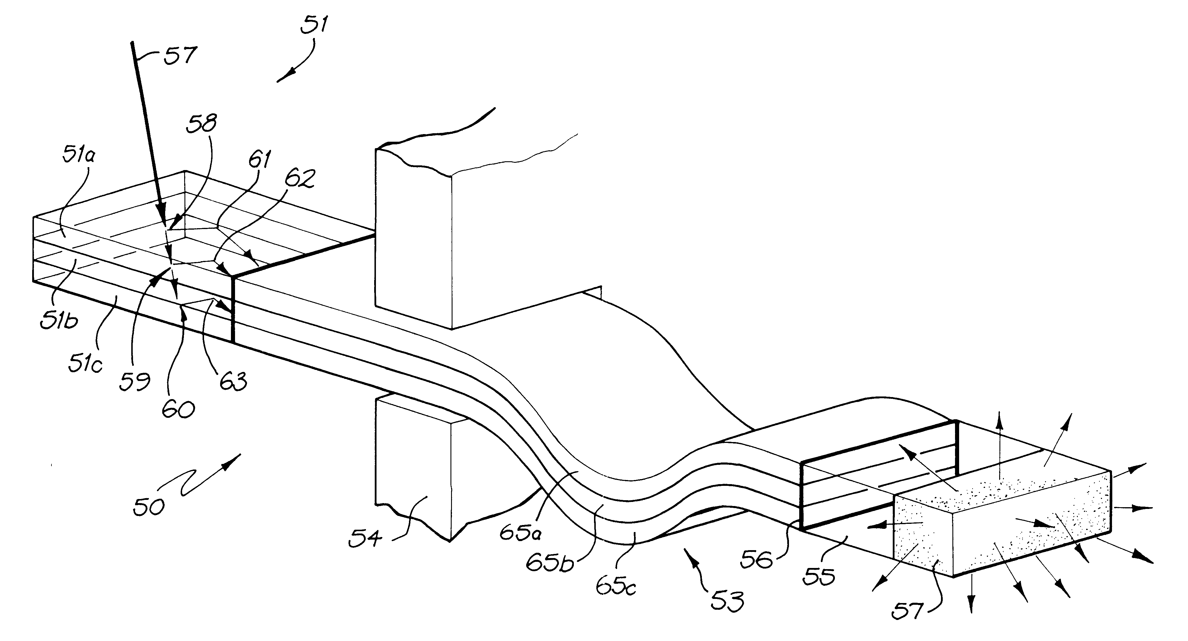
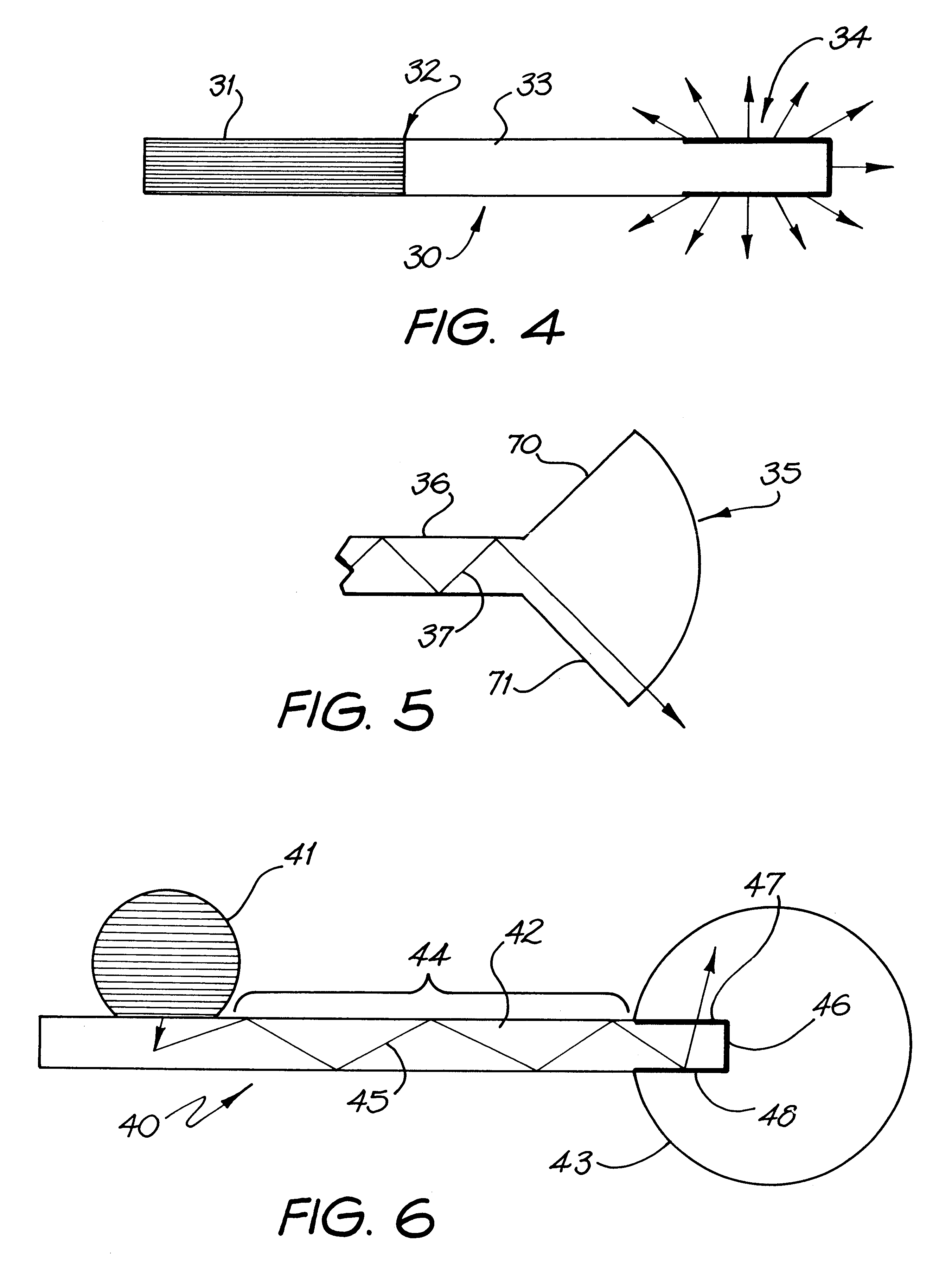
According to the present invention there is provided a lighting system for enabling release of trapped light therefrom as useful illumination, comprising a luminescent concentrator, an optical conduit optically coupled to the luminescent concentrator, and a luminaire means, the lighting system being fabricated of light propagating material and having surfaces which define an optically continuous solid optical system for enabling light to propagate therethrough by total internal reflection off the surfaces, wherein the said light is luminescent radiation emitted from the luminescent concentrator and wherein a portion of the said luminescent radiation would be, if it were not for the luminaire means, trapped in the optical system and unable to be released therefrom, the luminaire means comprising at least one region being so arranged as to allow the said otherwise trapped portion of the luminescent radiation to acquire an angle of incidence to the or each said region that will enable release of the said otherwise trapped portion of the luminescent radiation from the lighting system, whereby the quantity of light released by the lighting system as useful illumination is enhanced.
It is possible to eliminate the need for a coupling agent between the concentrator and conduit, by coating the luminescent material onto part of a continuous optical conduit or by casting the concentrator as a continuation of a preformed optical conduit, or by casting the optical conduit as a continuation of a preformed concentrator. Alternatively, the concentrator and optical conduit may be cast simultaneously.
However the joint from the luminescent concentrator to the optical conduit is made, it should ideally be defect free with no bubbles or voids and there should be no surplus coupling agent on the surfaces near the joint so that the lighting system is as optically continuous as possible and so that light may freely pass from the concentrator to the optical conduit without reflection or scattering. This optical continuity enables the `trapped light` (ie the light that would be trapped in the absence of optical continuity) to enter the optical conduit, whereas a simple alignment or butt joint, even with very smooth surfaces, would not.

Problems solved by technology

This light is completely trapped within the sheet and is unable to escape through any smooth surface of the sheet.
The prior art has not successfully provided a means by which this trapped light may be released from the conduit at a location where illumination is required.

Method used


Image

  • Lighting system for transmitting and releasing luminescent radiation
  • Lighting system for transmitting and releasing luminescent radiation
  • Lighting system for transmitting and releasing luminescent radiation

Examples


Embodiment Construction

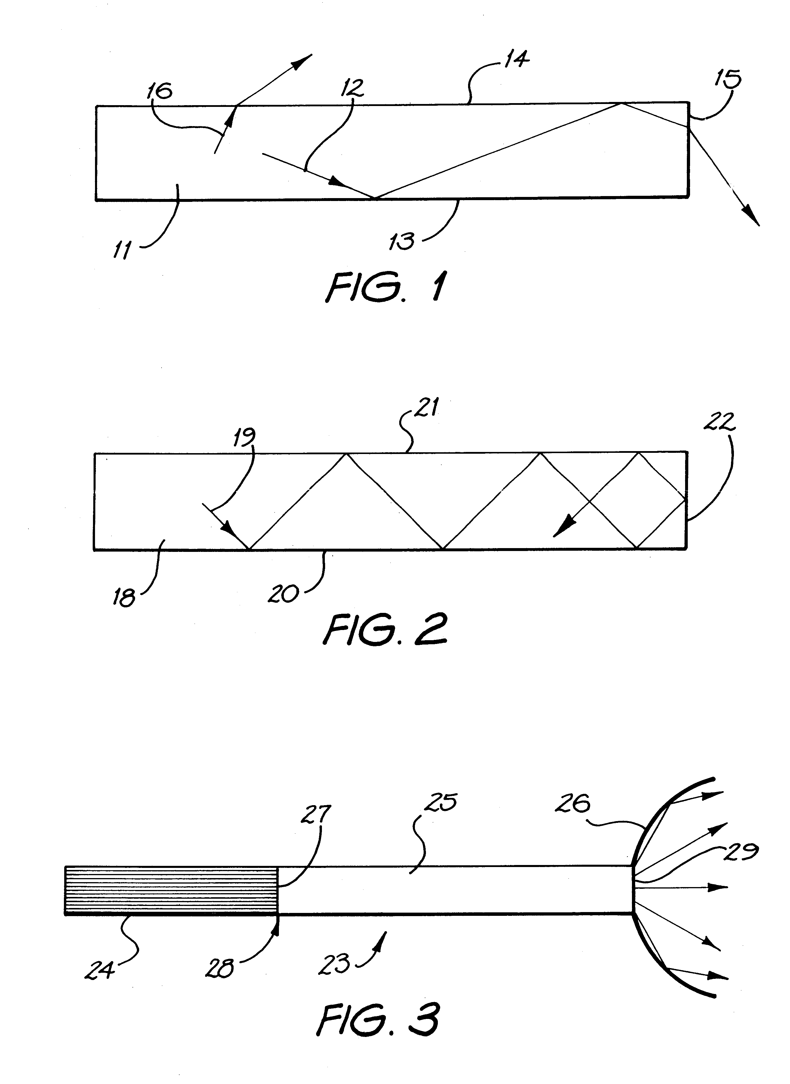
In the luminescent solar concentrator sheet 11 shown in FIG. 1, light 12 which is emitted by luminescent species (shown as the origin of the arrows) at small angles to the planar axis of the sheet 11 is totally internally reflected by the sheet's smooth lower surface 13 and smooth upper surface 14 and propagates to the end surface 15 where its angle of incidence and the refractive index at the interface enables it to be released or to escape from the sheet 11. Light 16 which is emitted by luminescent species nearly perpendicular to the planar axis of the sheet 11 immediately escapes through the upper surface 11 without undergoing total internal reflection.

In the luminescent solar concentrator sheet 18 shown in FIG. 2, light 19 which is emitted by luminescent species at intermediate angles to the planar axis of the sheet 18 is totally internally reflected by the sheet's smooth lower surface 20 and smooth upper surface 21 and propagates to the smooth end surface 22 where its angle of ...


PUM


Abstract

An optical conduit (53) for transmitting and releasing luminescent radiation (61, 62, 63) emitted from a luminescent concentrator (51), the luminescent concentrator (51) and optical conduit (52) comprising an optical system which is adapted to release to an area to be illuminated the luminescent radiation which is otherwise trapped in the optical system by total internal reflection. The optical conduit (53) includes a luminaire (57), such as a plurality of scattering regions for scattering trapped light so that the scattered light acquires the angle of incidence required to released from the conduit (53). The scattering regions may be provided by shape irregularities on the surface of the conduit (53) or inhomogeneities within the conduit (53). The conduit (53) may consist of flexible overlaid light guides (65a, 65b and 65c) and a luminaire fitting (55) optically coupled thereto.

Description

The present invention relates to a lighting system for transmitting and releasing luminescent radiation from luminescent concentrators or collectors and, in particular, to a lighting system in which trapped light generated from a luminescent solar concentrator may be transmitted and released.Such lighting systems have particular application as means for substantially increasing the useful light provided by a luminescent concentrator whose output is transmitted to the interior of a building by a clear, smooth, optical conduit. In particular, the invention seeks to provide a means by which light that is ordinarily trapped in the concentrator can travel down the conduit, and a means by which this light can be released from the conduit at a location where illumination is required.It is a fundamental principle of linear optics that no system in which all the light enters from outside the system can ever have any trapped light. It is the common general knowledge of persons skilled in the ...

Claims


Application Information

Patent Timeline
IPC IPC(8): F21V8/00F21S11/00G02B6/00F21S2/00G02B6/12
CPCF21S11/00G02B6/0008G02B6/0006Y10S385/901
Inventor FRANKLIN, JAMES BRUCE
Owner SKY SOLUTIONS
Learn More