
Power control method and cellular radio system

a power control and radio system technology, applied in power management, transmission monitoring, wireless communication, etc., can solve the problems of inability to achieve an accurate power control, difficulty in carrying out accurate power control, and extra attenuation

Inactive Publication Date: 2001-08-07
NOKIA NETWORKS OY
View PDF11 Cites 16 Cited by
  • Summary
  • Abstract
  • Description
  • Claims
  • Application Information

AI Technical Summary

Benefits of technology

An object of the present invention is to implement a solution according to which the step size to be used for power control is provided in such a way that the power control compensates for fadings occurring in the channel.
The cellular radio system according to the invention is characterized in that the means change the step size to be used for power control on the basis of the information on the speed of the subscriber terminal for diminishing fadings in the channel.
Considerable advantages are achieved by the method of the invention. The step size to be used for power control in a cellular radio system according to the invention is determined in such a way that the speed of the subscriber terminal is taken into consideration. In this way, the power control will be accurate. Simultaneously, the quality and the safety of a connection between the base station and the subscriber terminal of the cellular radio system will be better. Accordingly, the solution of the invention is capable of following the ideal power control better and diminishing the channel fading on the radio path, because the step size to be used for power control is changed on the basis of the speed information received from the cellular radio system.

Problems solved by technology

Therefore, subscriber terminals located close to the base station may cover a transmission of more distant base stations entirely, especially when the power control of the subscriber terminals is not accurate, because even a small correlation of a strong signal may cause a great interference to the indication of a weak signal.
It is, however, difficult to carry out an accurate power control, e.g. because of the quickly varying nature of a radio channel.
Slow fading of a signal is due to the fact that, on the radio path between the base station and the subscriber terminal, there is a varying amount of obstacles causing extra attenuation.
However, it has not been possible to achieve an accurate power control by the known power control methods so that fading occurring in the channel could have been decreased sufficiently.
These solutions have not considered the change in fading profile caused by a movement of the subscriber terminal.
As the step size used for power control in the known methods has been selected some compromise value, which has not been especially good at any speed of the subscriber terminal.
Consequently, the step size has worked at all speeds of the subscriber terminal, but it has not been anywhere near ideal at any speed.
Due to the above, the known power control methods have not been capable of following separate fading notches in the fading profile efficiently, which notches have occurred in the radio channel.
When the subscriber terminal has moved very slowly or stayed in place, the step size of power control used in the known solutions has usually been too big.
By too big a step size of power control, it has not been possible to adapt the ideal power control efficiently and accurately enough.
With increasing speed of the subscriber terminal, the step size to be used for power control has usually become too small for being capable of following efficiently fast fading, in particular.
If the speed of the subscriber terminal has grown even higher, the known power control methods have not been capable of following separate fading notches any more.
Moreover, it is not possible to follow said fading notches, because the frequency of occurrence of fading notches has been much greater than the possibility of transmitting power control commands, for instance.

Method used


Image

  • Power control method and cellular radio system
  • Power control method and cellular radio system

Examples


Embodiment Construction

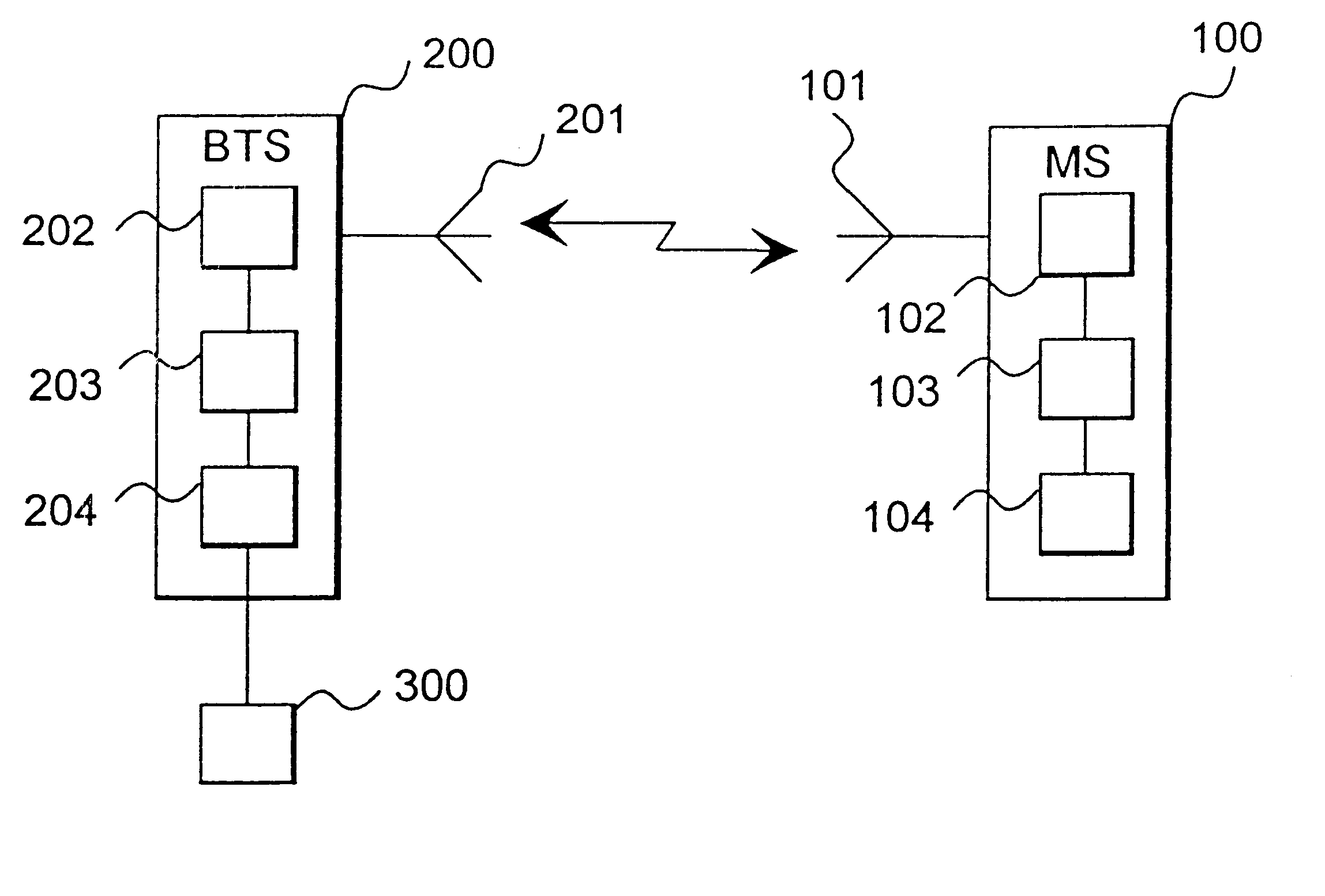
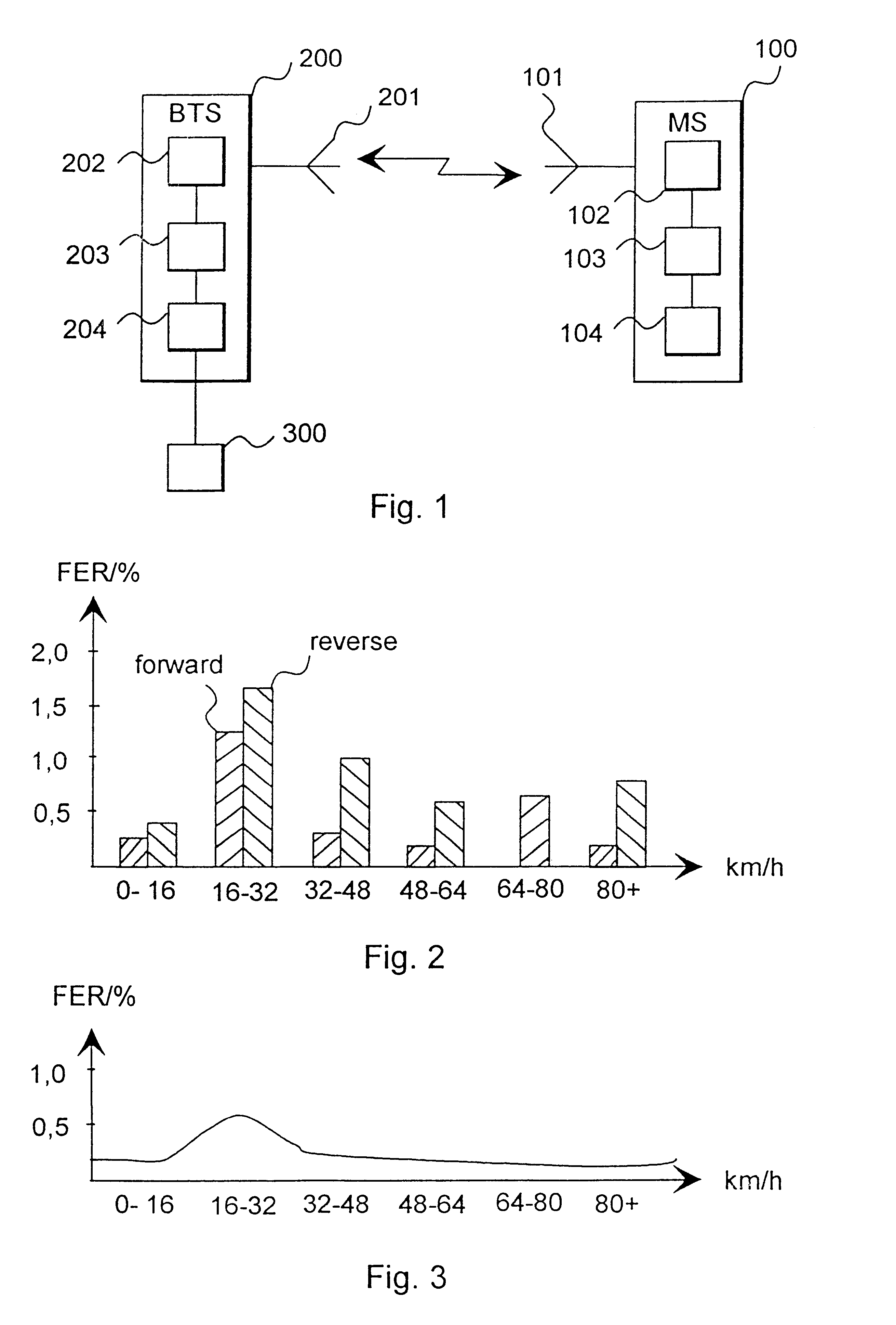
FIG. 1 shows a cellular radio system using the solution according to the invention. The solution of the invention is suitable for use in cellular radio systems based on CDMA technique (Carrier Division Multiple Access), in particular. The cellular radio system of the figure comprises a subscriber terminal 100, a base station 200 and means 300. In the solution of the figure, the means 300 are connected to the base station 200. The subscriber terminal 100 is connected to the base station 200 and the subscriber terminal 100 moves within the range of separate cells of the cellular radio system at a variable speed.

The subscriber terminal 100 comprises an antenna 101, radio frequency parts 102, D / A and A / D converter parts 103 and modulation parts 104. The antenna 101 works normally as a transceiver antenna. The subscriber terminal 100 receives by the antenna 101 a signal transmitted by the base station 200, which signal is applied to the radio frequency parts 102. The radio-frequency anal...


PUM


Abstract

The invention relates to a power control method and a cellular radio system used for power control, comprises at least one subscriber terminal, one base station and means for changing the step size to be used for power control. The means receive information on the speed of the subscriber terminal and the cellular radio system uses a fading channel. The means change the step size to be used for power control on the basis of the information on hte speed of the subscriber terminal for diminishing fading in the channel.

Description

FIELD OF TECHNIQUEThe invention relates to a power control method used for changing step size of power control in a cellular radio system, comprising at least one subscriber terminal and one base station, receiving information on the speed of the subscriber terminal and using a fading channel.The invention relates further to a cellular radio system used for power control and comprising at least one subscriber terminal, one base station and means for changing step size of power control, which means receive information on the speed of the subscriber terminal and which cellular radio system uses a fading channel.PRIOR ARTIn a cellular radio system, the quality of a connection between a base station and a subscriber terminal varies continuously. This variation is due to disturbing factors on the radio path and, for instance, to an attenuation of radio waves as a function of distance. The reception of the subscriber terminal is disturbed also by signals coming from base stations located ...

Claims


Application Information

Patent Timeline
IPC IPC(8): H04B7/005H04B7/26
CPCH04W52/362H04W52/282
Inventor LOKIO, JOUKO
Owner NOKIA NETWORKS OY
Learn More