Unit for tying a balloon and securing a ribbon to the balloon

a technology for tying a balloon and a ribbon, which is applied in the field of tying a balloon unit, can solve the problems of manual dexterity, limit the speed at which such an operation can be carried out, and difficulty in completing a task, so as to achieve easy inflated and move easily and quickly.

Inactive Publication Date: 2001-08-14
CARLSON LELAND R
View PDF16 Cites 25 Cited by
  • Summary
  • Abstract
  • Description
  • Claims
  • Application Information

AI Technical Summary

Benefits of technology

The unit is mounted on a tank of gas used to inflate balloons adjacent to the exhaust valve of the tank. A balloon is easily inflated using the exhaust valve of the tank and is then easily and quickly moved to a position to be wrapped around the supporting bracket and the ribbon.

Problems solved by technology

This is often a difficult task, especially if speed is required as is often the case in a situation where a great number of inflated balloons are to be provided.
Tying an inflated balloon requires some manual dexterity, and there is a limit to how fast such an operation can be carried out.
However, these known systems are often cumbersome, expensive and difficult to use.
Still further, many such known systems are not entirely and efficiently amenable to use on a tank of pressurized gas.
Furthermore, many of these known systems are fragile.
Attaching a ribbon to an inflated balloon adds yet another difficultly to the above-discussed problems.
While the art does contain systems for sealing an inflated balloon and attaching a ribbon to such sealed balloon, these known systems are often cumbersome, fragile, difficult to use and are not amenable to use in a variety of situations.
This makes such known systems inefficient.
Still further, many of these known systems; are not amenable to packaging with ribbon to be sold as a kit.
Therefore, their use is somewhat limited.
Still further, if a prior art system supports a spool of ribbon, that ribbon is often supported in a position that is not as stable as it could be.
If a spool of ribbon is pulled off its support, the overall process is slowed down, or the ribbon may be damaged or soiled, all of which are wasteful.
Still further, many known systems are designed for use by a right-handed person and are very difficult, if not impossible, for a left-handed person to use.
Many known systems can only be efficiently used with large cylindrical tanks.
This limits the number of situations in which these known systems can be efficiently used.

Method used


Image

  • Unit for tying a balloon and securing a ribbon to the balloon
  • Unit for tying a balloon and securing a ribbon to the balloon
  • Unit for tying a balloon and securing a ribbon to the balloon

Examples


Embodiment Construction

Other objects, features and advantages of the invention will become apparent from a consideration of the following detailed description and the accompanying drawings.

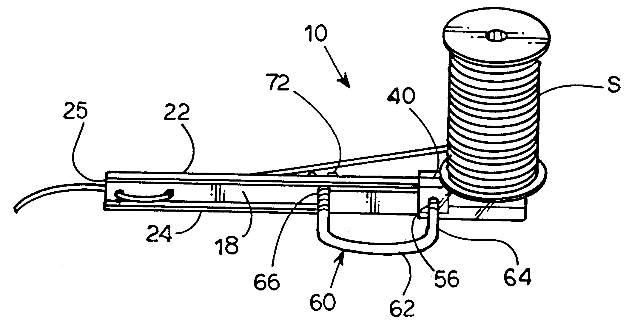
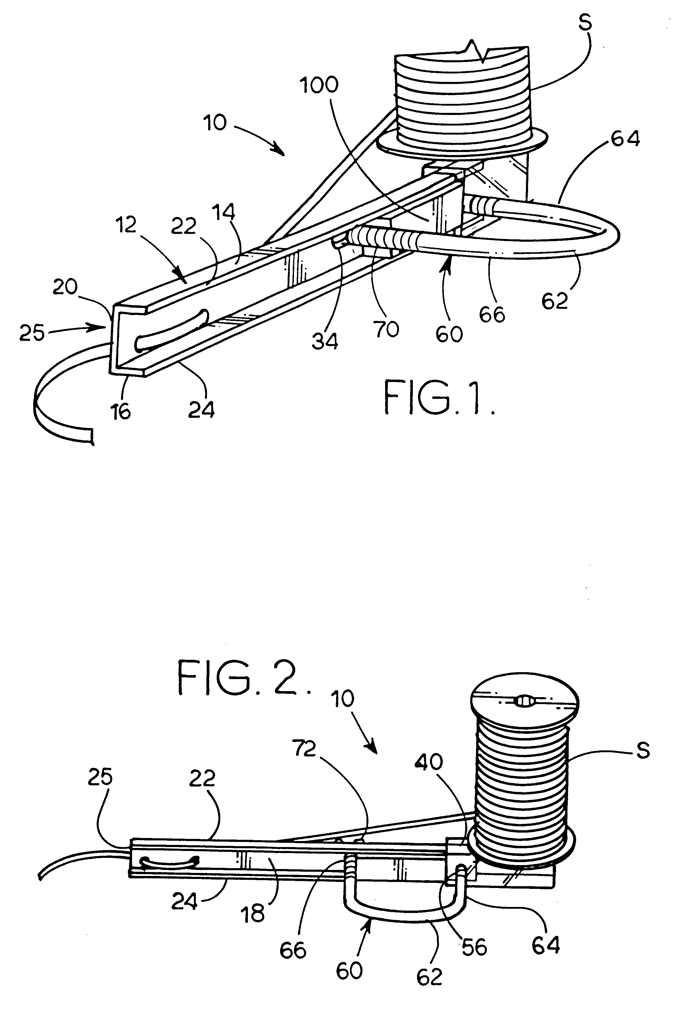
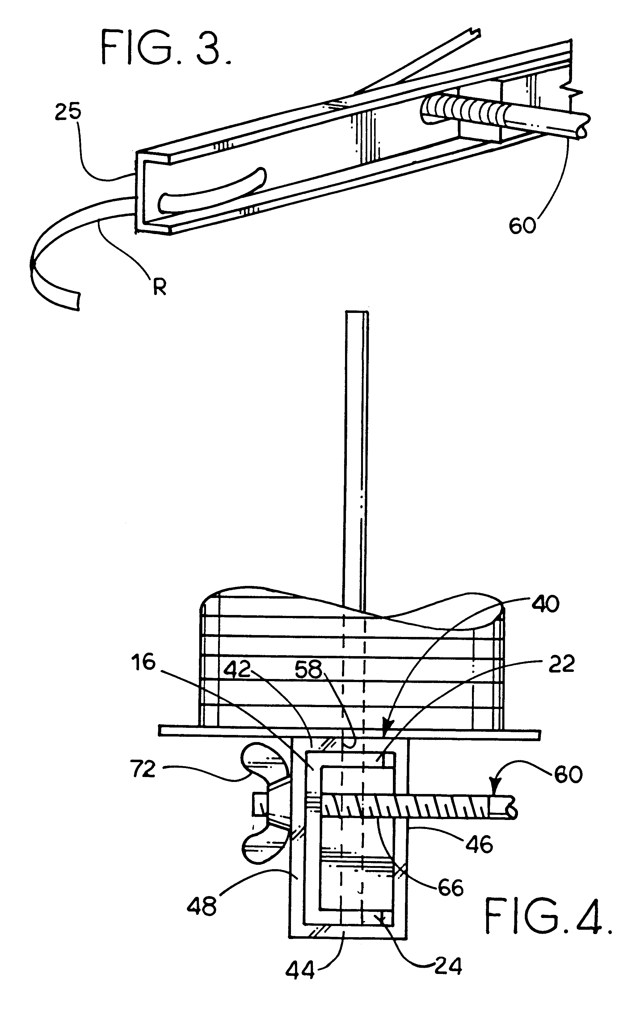
Referring first to FIGS. 1-7, a unit 10 is used to tie a ribbon R from a spool S to a balloon B (see FIGS. 12, 13 and 15). Unit 10 includes a supporting bracket 12 that has a one-piece section 14 that is formed of metal or plastic as suitable. It is noted that plastic may be less expensive to manufacture than metal and may make it easier to manipulate a balloon neck as will be understood from the following disclosure.

Section 14 includes a central section 16 having an inside surface 18 and an outside surface 20 and two side portions 22 and 24 that extend parallel to each other and which, together with central section 16, form a U shape. Section 14 is elongate and has a distal end 25 and a proximal end 26 (best shown in FIG. 7) and a longitudinal dimension CL extending from distal end 25 to proximal end 26.

As best shown i...


PUM


Abstract

A unit is mounted directly on a tank of pressurized gas used to inflate a balloon and includes a supporting bracket having ribbon-accommodating holes defined through one end thereof and a support section on the other end. A ribbon supporting spool is rotatably mounted on the support section and ribbon drawn off the spool is threaded through the ribbon-accommodating holes to be captured in a knot formed in the neck of the balloon after that neck has been drawn around the supporting bracket and formed into a knot. A method of forming a knot in the balloon and capturing the ribbon therein is also disclosed.

Description

The present invention relates to the general art of amusement devices, and to the particular field of inflatable toys having an externally applied sealing element as well as to the field of knot tying and means peculiarly adapted to assist the hand or operated by hand to form a knot by forming a loop through which a portion of a the inflatable toy is passed and the loop tightened.Many situations include providing balloons for people. Examples of such situations include parties, fairs, promotional activities and the like. Often, a multiplicity of balloons must be inflated and sealed. This is often a difficult task, especially if speed is required as is often the case in a situation where a great number of inflated balloons are to be provided.The situation involving inflating and sealing a multiplicity of balloons generally requires use of a tank of pressurized gas. Each balloon is placed over an exhaust nozzle of the tank, a valve opened, the balloon inflated to a desired size and th...

Claims


Application Information

Patent Timeline
Patent Type & Authority Patents(United States)
IPC IPC(8): A63H27/10A63H27/00
CPCA63H27/10
Inventor CARLSON, LELAND R.
Owner CARLSON LELAND R
Why Eureka
Try Eureka