Light regulation device

a technology of light regulation and light source, which is applied in the direction of lighting and heating apparatus, instruments, mechanical apparatus, etc., can solve the problems of catching foreign objects, affecting the performance of lighting, and the illuminance of the lower part of the lamp, and achieves the effect of convenient manufactur

Inactive Publication Date: 2001-08-14
ENPLAS CORP
View PDF18 Cites 80 Cited by
  • Summary
  • Abstract
  • Description
  • Claims
  • Application Information

AI Technical Summary

Benefits of technology

An object of the present invention is to provide a light regulation element which is easily manufactured. And, another object of the present invention is to provide a light regulation element which, while regulating the travelling direction of a light emitted from a surface light source de

Problems solved by technology

Also, where a surface light source device is used for a local illumination for illuminating a specific area, the more diffused the light, the wider area the device can illuminate, but the lower the illuminance becomes.
If foreign matters such as dirt and dust adhere onto optical parts, or a flaw occurs thereon, the performance thereof will be remarkably deteriorated

Method used


Image

  • Light regulation device
  • Light regulation device
  • Light regulation device

Examples


Embodiment Construction

As a method of evaluating the ability of the light diffusion layer coated on the light regulation element, the turbidity described below can be used. With reference to FIG. 4, a method of measuring the turbidity will be explained.

First, as shown in FIG. 4(a), a He--Ne laser beam 8 is irradiated vertically onto a transparent substrate 7 and the intensity of the light 9, a part of the light penetrating the transparent substrate 7, which penetrates in a direction perpendicular to the transparent substrate 7 is measured. The value thus obtained is taken as I.sub.0.

Then, as shown in FIG. 4(b), with the light diffusion layer 5 having thickness of d cm coated on the transparent substrate 7, the He--Ne laser beam 8 is irradiated vertically onto the transparent substrate 7 in the same manner as in FIG. 4(a), and the light intensity of light 9', a part of the light penetrating the transparent substrate 7 and light diffusion layer 8, which penetrates in a direction perpendicular to the transpa...


PUM


Abstract

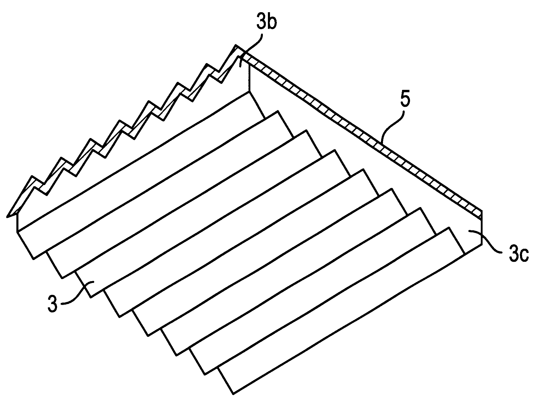
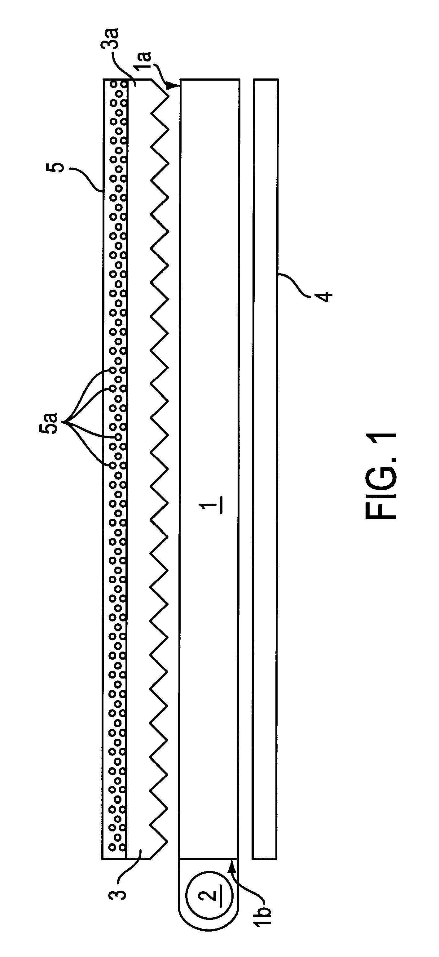
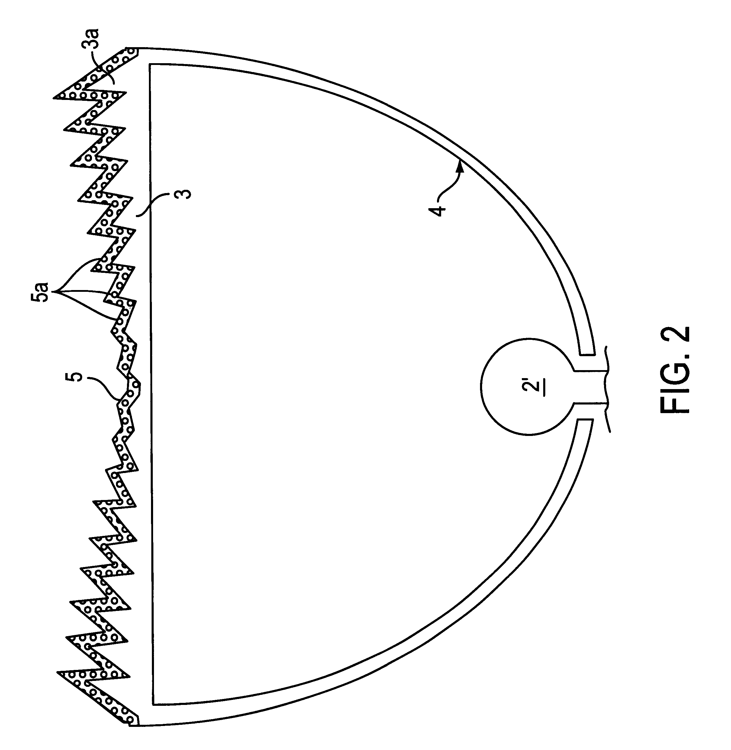
A light regulation element regulates both the travelling direction and diffusion state of a light emitted from a surface light source device. Lights from a cylindrical light source 2 such as a cold cathode tube is introduced in a light guide 1. The light guide 1 has an emission surface 1a on the side opposite to a reflection element 4, and a light regulation element 3 is arranged in opposition to the emission surface 1a. Protrusions 3a are formed on one surface or both surfaces of the light regulation element 3. Coated on the surface on the light emission side of the light regulation element 3 is a light diffusion layer 5. The turbidity of the light diffusion layer 5 falls within a range from 1900 cm-1 to 2400 cm-1 . The light emitted from the emission surface 1a of the light guide penetrates the light regulation element 3, thereby causing the light travelling direction to be regulated. Then, the light whose travelling direction has been regulated penetrates the light diffusion layer 5, thereby causing a light diffusion. The light diffusion layer 5 is formed, for example, by mixing fine particles of a glass having a light penetrability or of a synthetic resin such as acryl and silicone, or fine hollow particles of glass, acryl resin or the like, or air bubbles in a coating material having a light penetrability.

Description

1. Technical FieldThe present invention relates to a light regulation device for regulating the travelling direction of light. and more particularly to a light regulation element for regulating the travelling direction of the light emitted from a surface light source device.2. Description of Related ArtWhere a surface light source device is applied to the backlight of a liquid crystal display, a range in which the display contents of the liquid crystal display can be clearly and visually recognized, that is, a view angle, and a brightness observed when the display screen is watched are affected by the travelling direction and spread of the light emitted from the surface light source device.The more diffused the light emitted from the surface light source device, the wider the view angle becomes, but the darker the display becomes.On the contrary, the less diffused the emitted light, the narrower the range of view angle becomes, but the larger the quantity of the light travelling in ...

Claims


Application Information

Patent Timeline
IPC IPC(8): F21V8/00G02B5/02G02B6/00G02F1/1335G02F1/13357
CPCG02B5/0242G02B5/0247G02B6/0053G02B5/0278G02B6/0051G02B5/0263
Inventor ARAI, TAKAYUKIWATAI, KAYOKO
Owner ENPLAS CORP
Why Eureka
Try Eureka